
TLDR: Predicting aerodynamic damping through simulation is possible by combining ANSYS Mechanical and ANSYS CFX. This method can be use for turbine blades, aircraft wings or MEMS micro mirrors!
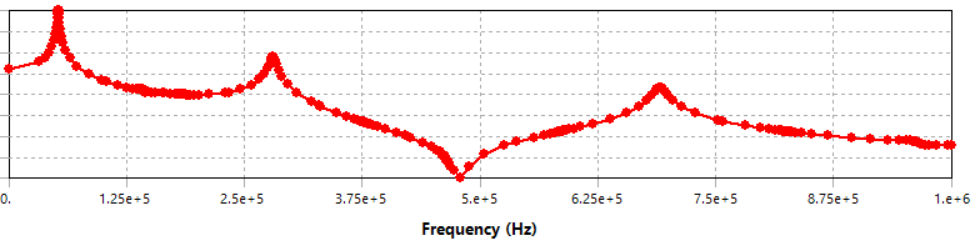
Frequency response of a MEMS system. The height of the peaks depends on the damping… so what’s the damping ratio?
Over the years, many people have asked me “Hey Ming, can we use simulation to predict damping?” Si Se Puede!
Damping is one of those important values in mechanical dynamics that’s usually gathered through measurement and simulation correlations. But many of my friends work on MEMS devices and it is really hard to stick an accelerometer onto a MEMS accelerometer!
Thus, calculating damping through simulations becomes very handy. - see video below!
So let’s do it.
Overview
The process is as follows:
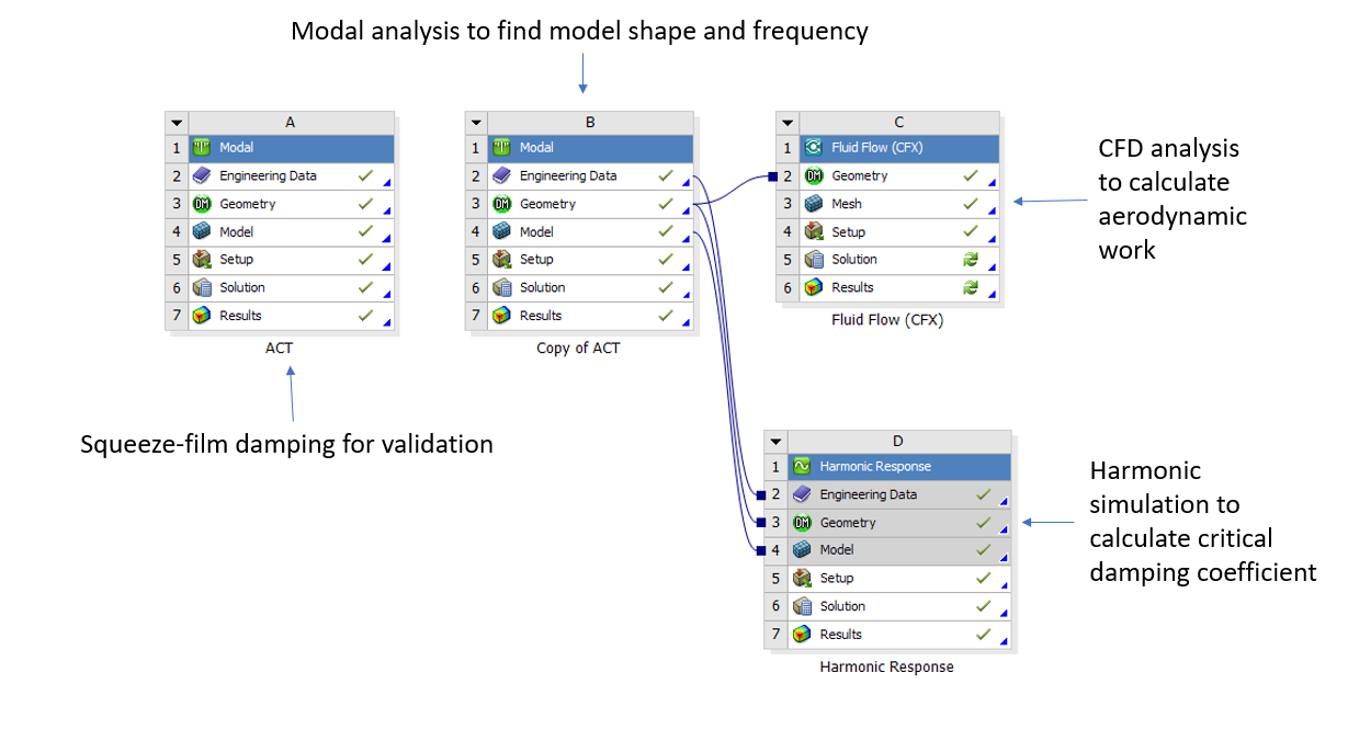
ANSYS Workbench project schematic makes the process crystal clear!
Perform a structural modal analysis and pick out the mode shape of interest. If you are designing resonators, you know the one you want.
Map the motion of the mode shape onto a transient CFD simulation and run a few cycles.
Calculate the work done to the fluid and divide it by the critical damping.
Voila! You have a damping ratio.
Seems easy? … not really. There is a lot of stuff in there that need to be automated.
Luckily for all of us it’s already done in ANSYS.
In an effort to bring damping calculations to turbo mech, the ANSYS dev team did all of the hard work. We can just piggy back on their effort to make this work for MEMS as well.
Example
Here we have a squeeze film damping problem.
Picture a gold beam that vibrates up and down and there are some holes that lets the air through.
This is a standard example that we use because we’ve got a squeeze film damping model in ANSYS Mechanical as well.
First let’s do a modal analysis.
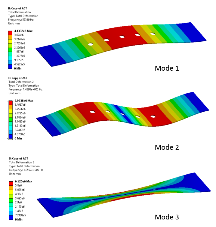
Which mode is the one of interest? Some of these don’t really look like squeeze film damping anymore eh?
We call a special function to export a CFX deformation profile. This means all of the mesh motion and deformations get taken care of, for us! (See, I told you the dev team did all of the hard work!)
set,1,1,,real
cmsel,,Beam
expr,surf,mode,,Beam,BeamMode1,csv
Then we start a computational fluid dynamics simulation in CFX.
We are going to do a “transient blade row model.” But not really, because we are doing a squeeze film damping simulation. We pretend it is a transient blade row model because this is where much of damping calculation features are stored.
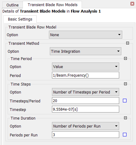
Transient cyclic simulation settings
It kind of makes sense if you squint your eyes a bit, fourier transform, cycles, periods… damping!
Load our .csv in as a profile and turn on mesh deformations etc.
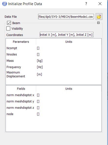
Automatically import motion data from the modal analysis.
Magically, aerodynamics damping appears as an option in the monitors window.
This will automatically do the cyclic integration of work done by the move blade in a transient CFD simulation.
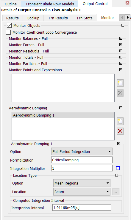
Aerodynamic damping automatically calculated
We do need to first define a critical damping coefficient though, because we want a damping ratio. This is 4*pi*TotalEnergy.
We can get the total energy for the particular mode shape from a harmonic simulation. Just excite the structure to vibrate at the amplitude we want to read it off the screen.
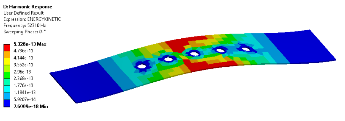
Harmonic analysis of 1st mode - kinetic energy plot
Now we are good to go.
Wait a while for the simulation to complete and we have the damping ratio!
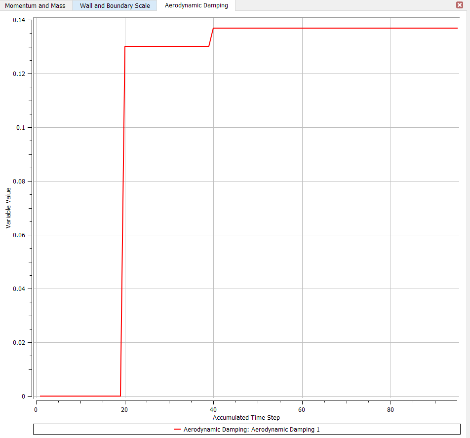
Damping calculated over each cycle
Conclusion
I’ve been wanting to go through this for a couple of years now so it’s great to finally get this done.
In addition to squeeze and slide film damping, this method opens up a wide range of options for damping ratio calculations. Torsional motion is often of interest and now there is a way to calculate damping ratio. - Check out the example below.
Found this useful?
Heart us below.