
Introduction
Isogeometric analysis (IGA) is an emerging technology in the world of computational mechanics that bridges the gap between computer-aided design (CAD) and finite element analysis (FEA). In traditional FEA workflows, the CAD geometry is approximated using linear polynomials in a time intensive meshing process, whereas in IGA the same spline basis functions are used for both the geometry definition and for analysis. This means that an exact geometry representation is used for the analysis. Other potential benefits include a faster development process, higher predictive accuracy per degree of freedom and increased efficiency compared to traditional FEA.
Why use IGA in LS-DYNA?
IGA capabilities have been present in Ansys LS-DYNA since 2008 and are continuously being developed and expanded. There is a family of *IGA control cards that provide a clear separation of geometry and topology to define IGA parts. Most of the existing LS-DYNA cards can be used in an analysis with IGA parts including but not limited to:
- Explict and implict analysis
- Most material models
- Damage and failure
- Boundary conditions and loads
- All penalty based contacts
- Connections (spot welds, tied contact etc)
Additionally, Ansys LS-PrePost can be used to create IGA shells and solids from CAD data and visualize the results using the standard d3plot file.
In this blog post we will walk through a simple example of setting up an IGA model in LS-PrePost and running in LS-DYNA.
Example Problem: Crashbox
The goal of this example is to simulate the crushing of a simplfied crashbox using IGA parts in LS-DYNA. We start with the geometry in STEP format. The geometry file is available in the download link at the bottom of the post. Note that we will using IGA shells, so the geometry we start with is a midsurface that was created in CAD software.
Create NURBS patch
After importing the STEP file into LS-PrePost (use version 4.9 or newer) , the first step is to create a NURBS patch for our geometry. This can be done by accesing the the NURBS Editor under Element and Mesh -> Nurbs Editing. Make sure the option is set to Create and select all the faces on the part. An easy way to do this is to use the Whole option in the Sel. geom dialog box. After hitting apply you will see the control points for the NURBS patch appear. Then choose accept. This will create one NURBS surface for each CAD surface in the part.
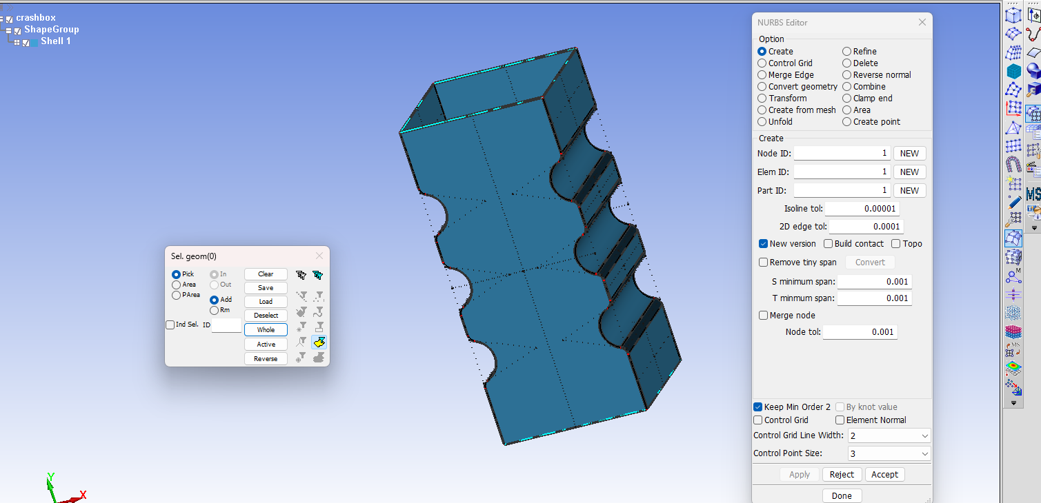
The next step is to refine the NURBS mesh. The higher degree and higher continuity of IGA spline based elements will generally allow for larger element sizes compared to traditional finite elements, but we will still need more than one element per surface on this geometry. To refine the mesh just select the refine radio button under the Option heading in the NURBS editor. There are several options for refining methods and the option that is most similar to traditional mesh refinement is H-refinement, which is simply refining the element length. To perform the refinement we again select all the elements and enter a span, or length, of 5 in both the R and S direction. Hit appy to see the effect and then accept to confirm the action. If a warning box apprears about overwriting data choose Replace All.

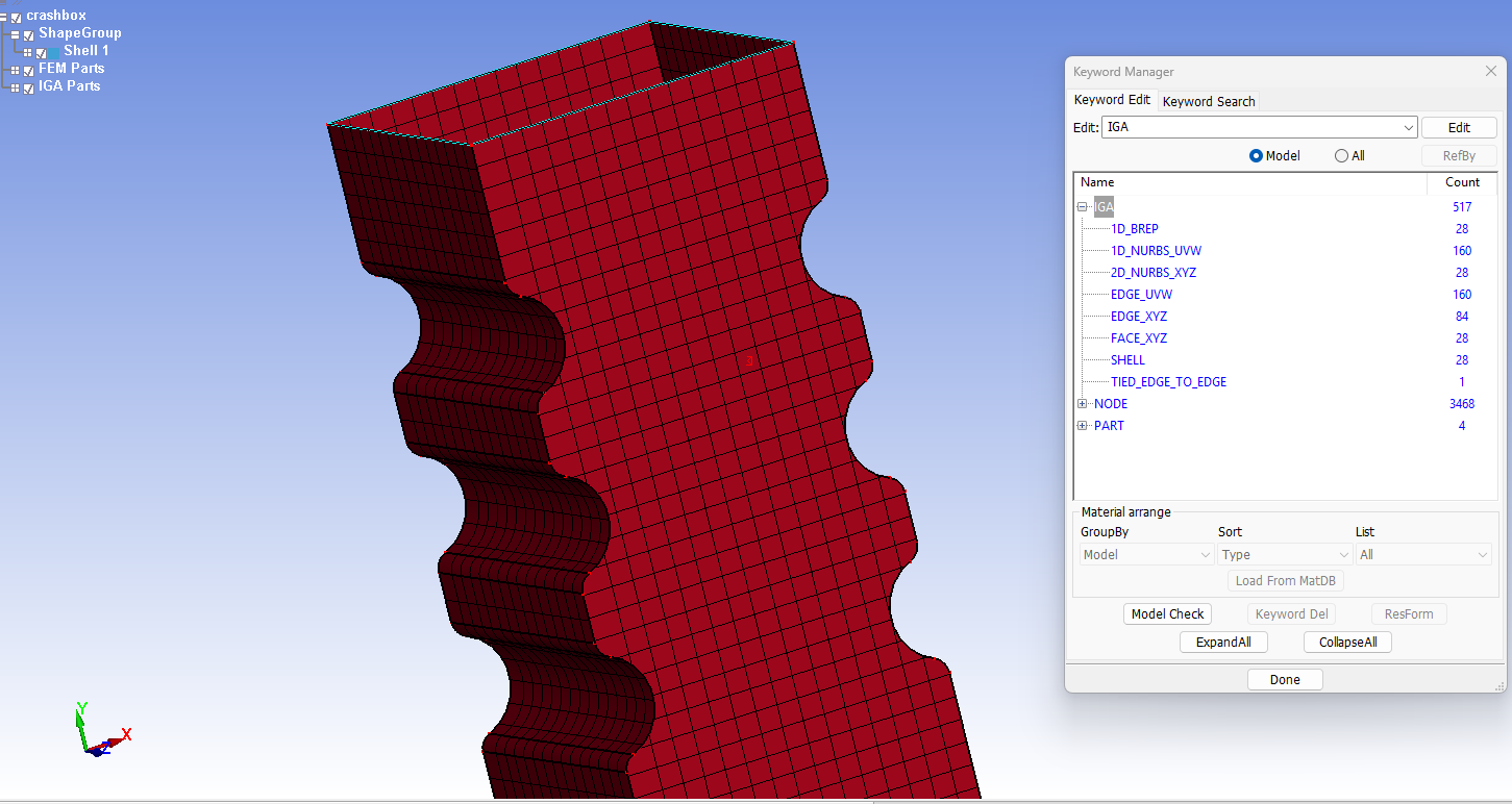
After these operations finish you will notice that there are new objects called FEM Parts and IGA parts in the model tree. Additionally, looking that the cards currently in the model using the Keyword manager will show many cards created under the *IGA heading. These cards have been automatically created by LS-PrePost to define the IGA geometry for analysis.
Assign section, material and boundary conditions
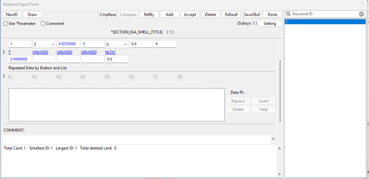
The next step is to define a *SECTION_IGA_SHELL card that will be used to define the section for the parts in our model. The specific parameter values used in this example are shown below.
From this point the model setup proceeds in the same way as a traditional finite element model. The cards used for material and boundary conditions are listed below and the specific parameter values can be referenced in downloadable input files which can be accessed via the link at the end of this post.
- *DEFINE_BOX - used to select nodes on the top and bottom rims of the crashbox
- *SET_NODE_GENERAL - create node sets for the nodes on the top and bottom rims of the crashbox, using the boxes.
- *BOUNDARY_SPC_SET - used to fix the bottom of the crashbox
- *RIGIDWALL_PLANAR_MOVING_FORCES - rigidwall used to crush the crashbox
- *CONTACT_AUTOMATIC_SINGLE_SURFACE - interpart contact for reaslistic crush of the crashbox
- *MAT_PIECEWISE_LINEAR_PLASTICITY - see input files for details
Also remember to put input the material and section IDs in the *PART card.
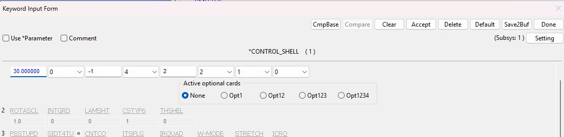
Recommended control settings
In addition, the following parameters for *CONTROL_SHELL work well for this simulation.
Conclusion
This post just scratches the surface of the IGA capabilites that are present in LS-DYNA. This model uses what are called trimmed multi-patch NURBS shells, in which the the model has multiple trimmed NURBS shell patches that are conneted with tied contact definitions. LS-DYNA is also capable of simulating with trimmed multi-patch NURBS solids, as well as boundary fit spline shells and solids. The capailbites may be covered in future blog posts.
Downloadable Content:
LS_DYNA_IGA_CRASHBOX.zip
Ozen Engineering Expertise
 Ozen Engineering Inc. leverages its extensive consulting expertise in CFD, FEA, optics, photonics, and electromagnetic simulations to achieve exceptional results across various engineering projects, addressing complex challenges like multiphase flows, erosion modeling, and channel flows using Ansys software.
We offer support, mentoring, and consulting services to enhance the performance and reliability of your systems. Trust our proven track record to accelerate projects, optimize performance, and deliver high-quality, cost-effective results for both new and existing water control systems. For more information, please visit https://ozeninc.com.