
Abstract
This blog goes over some of the features of Ansys Sherlock. It goes over the process of importing a PCB, setting up and running different analyses, then making modifications to the PCB for it to meet reliability standards.
Introduction
Sherlock is an analysis tool by ANSYS that allows engineers to quickly analyze the behavior of printed circuit boards (PCBs). With Sherlock, we can evaluate the behavior of PCBs under various events, such as vibration, shock, and thermal cycling. Sherlock will also allow us to predict the lifetime of the PCB, and what events contribute to component and board failure.
Opening Sherlock
When you open sherlock, you’ll be able to see projects on the left side of the screen.
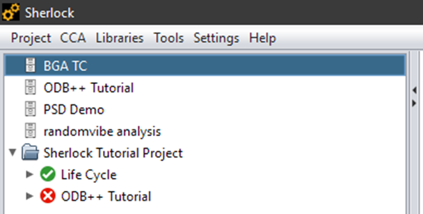
You can navigate to the project tab to import a variety of different file types, including EDB, ODB Archive, ODB XML Archive, IPC -2581, CADIF, Eagle, and GDSII Files.
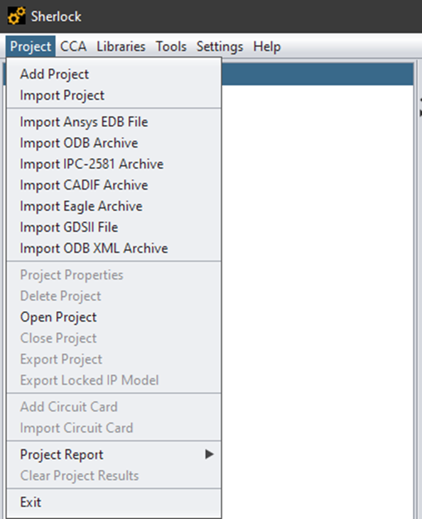
When importing a project, there are some additional options we can modify. In this example, I am using a tutorial board located in: C:\Program Files\ANSYS Inc\v232\sherlock\tutorial
We will need to click “Scan Archive”, then click “Import Archive”. This will import all of the components, layers, and drill holes of the board.
Setting up the PCB
Before we start analyzing the board, we will want to make sure that we have all of the parts we need. Right click on “Parts List”, and select update parts list from part library. Turn on the part wizard.
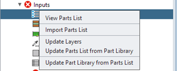
This will update the components and their properties. We can double click on “Parts List” to verify that all of our components were correctly characterized.
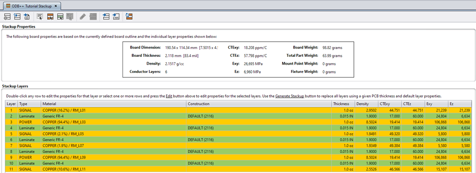
We can also double click on “Stackup” to view the PCB material properties. We can modify the material composition and properties of a layer by right clicking or double clicking. Sherlock has a database of various laminates and other materials that we can use to define our PCB stackup.
There are additional tools we can use to manipulate the PCB before we begin analyzing it.
If we double click on Pick and Place or Drill Holes, we can open up a view of the PCB. We can make various edits to the board by going to the edit tab, and selecting our desired change to make.
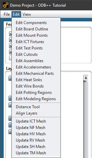
We can change component orientation and location, add or remove drill holes and mounting points, and more. These options can be helpful for us to quickly test the effects of changing certain parameters, such as adding additional mount points or changing a component orientation to reduce stress along a certain axis.
Analyzing the PCB
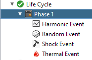
Under the Life Cycle tab, we can define different shock, vibration, and thermal loads for the PCB.
Once we have defined our PCB and the different events, we can start to run our different analyses. We can right click on Analysis, then pick the option to run all tasks.
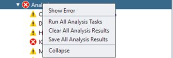
Another approach is to right click on individual tasks to run them individually.
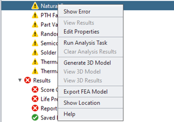
When we select Run Analysis Task, it opens up a menu that allows us to make additional changes to our analysis settings.

After we select save and run, the analysis task will begin. After it is completed, we can right click on the analysis and view results. There may be some warnings, but we can still view the results.
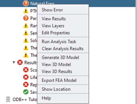
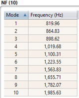
The natural frequency analysis generates the natural frequencies of the PCB.
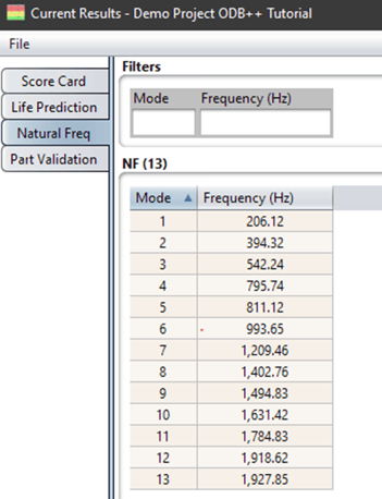
We can view the mode shapes by selecting “View 3D Results.” When in the Sherlock 3D viewer, we can change which mode shape we are looking at by selecting them in the Color Schemes tab, and clicking refresh.
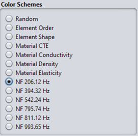
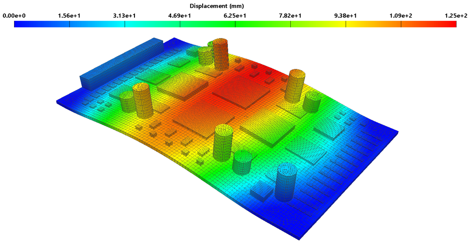
Figure 1: Mode Shape at 206.12 Hz
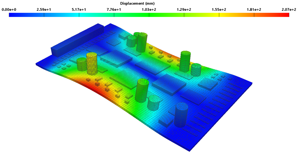
Figure 2: Mode Shape at 394.32 Hz
The above images are for the first two mode shapes. The displacements for mode shapes represent areas where we can expect the board or component to deflect.
We can also get lifetime predictions of our component after we have run our different analyses. For this example, I have run a Solder Fatigue analysis. Solder Fatigue will use the thermal event defined for its fatigue analysis.
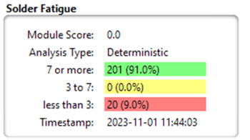
Our score card for solder fatigue indicates that most of our components will last for our desired timeframe, but that a handful will not. We can go to a table view to see which components are failing.
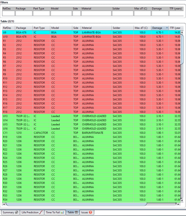
Sherlock also provides a Time to Fail (TTF) for each component, and uses that to predict when a given component will fail as shown in the below image.
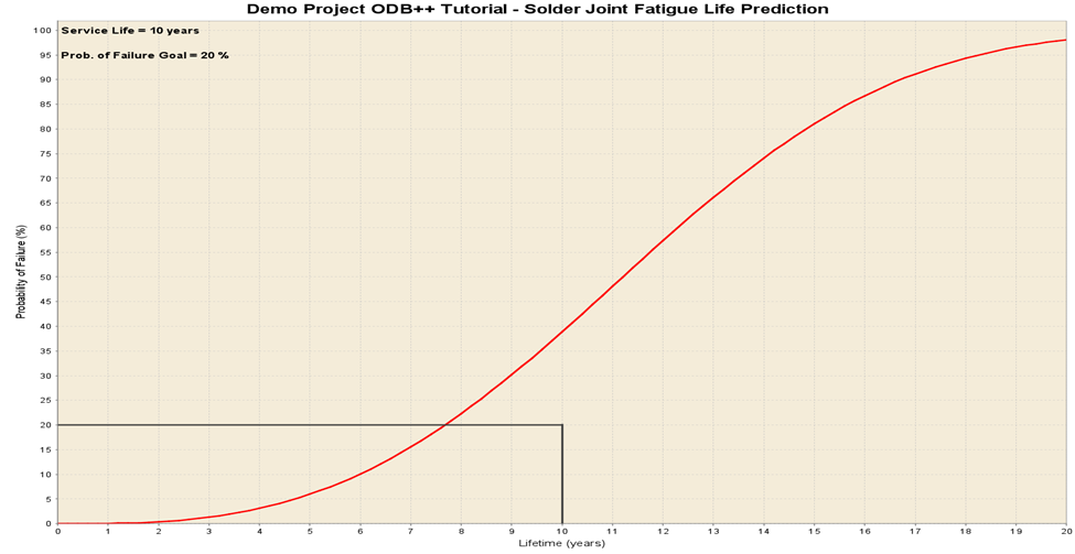
Figure 3: Solder Joint Fatigue Life Prediction
As shown, we may need to modify the solder properties for the indicated components to meet our requirements.
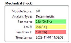
I decided to run the other analyses to see what issues arise. The Mechanical Shock analysis indicates that one component is likely to fail. The table view indicates the failure type is due to overstress, and the TTF is >100 years. We may not need to worry about this component depending on the application of the board.

When we look at the results, we can see that the component has higher stresses in the corners.
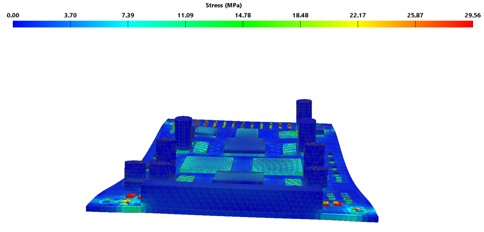
Figure 4: Mechanical Shock Stress Results
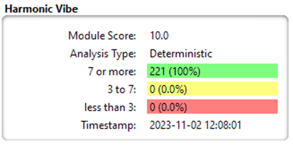
I also ran the Harmonic Analysis, which indicated that multiple components are likely to fail.
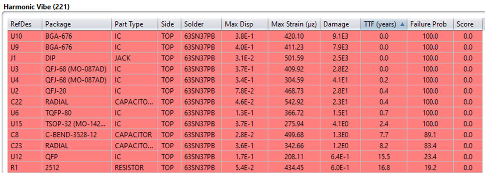
We can use the "SH Comp Score" to view components that will fail. In the image below, red components will fail before our specification of 20 years.
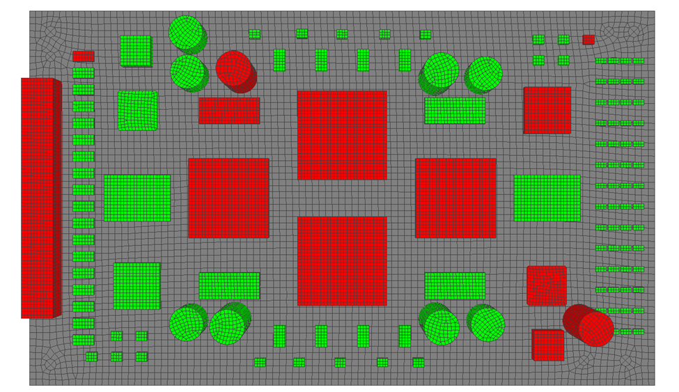
Figure 5: Mechanical Shock Component Failure
In our strain analysis, we can see that several components have high stresses and strains, which likely contributes to their failure.
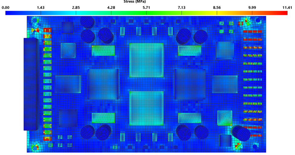
Figure 6: Mechanical Shock Strain Results
The displacement results indicate higher displacement in the center of the board, which likely contributes to the components in the center failing.
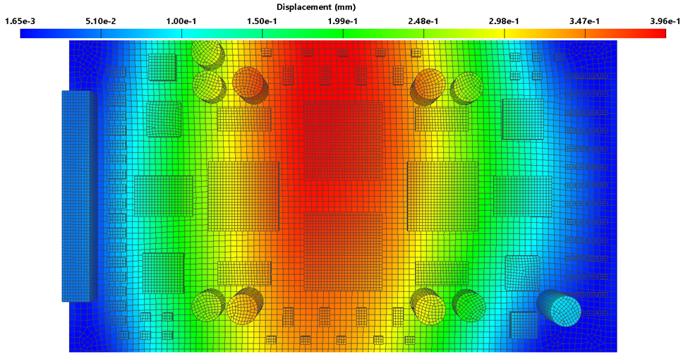
Figure 7: Mechanical Shock Displacement
Sherlock can make a life prediction based on the different loads that we have applied. The below plot shows the individual life predictions of each analysis type, and a combined life prediction. The harmonic vibration analysis is dominant, and overlaps with the combined life prediction.
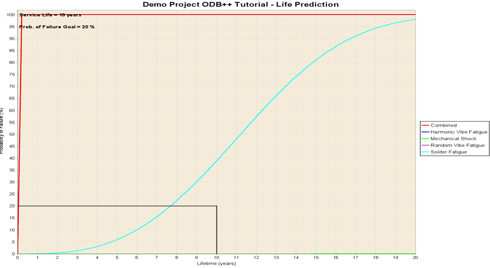
Figure 8: Combined Life Prediction
Our preliminary analysis suggests that solder fatigue and harmonic vibration are dominant. What can we do to remedy this?
Modifying the PCB
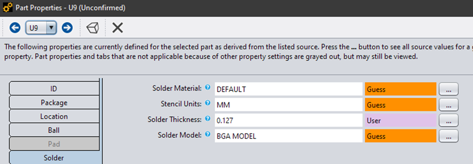
We'll start with resolving the solder fatigue. We can select all of the failing components and modify them all at once. We'll start by doubling the solder thickness and re-run the solder fatigue analysis.
We have resolved the issues with the resistors, but the BGA packages are still failing.

Lets try a more flexible solder instead. I've picked through Sherlock's solder library and picked out one with the lowest elastic modulus.

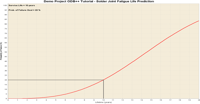
Figure 9: Mechanical Shock Component Failure
We are close to meeting our requirements. Lets try increasing the ball height.
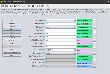
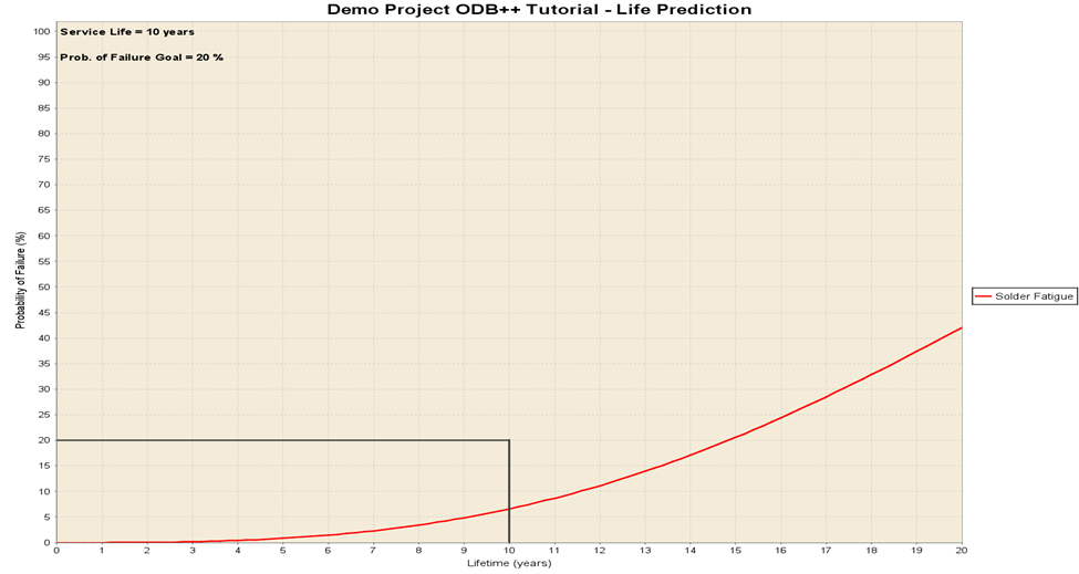
Figure 10: Solder Fatigue Life Prediction
Our board now meets our solder fatigue requirements. Lets work on fixing our harmonic vibration issues.
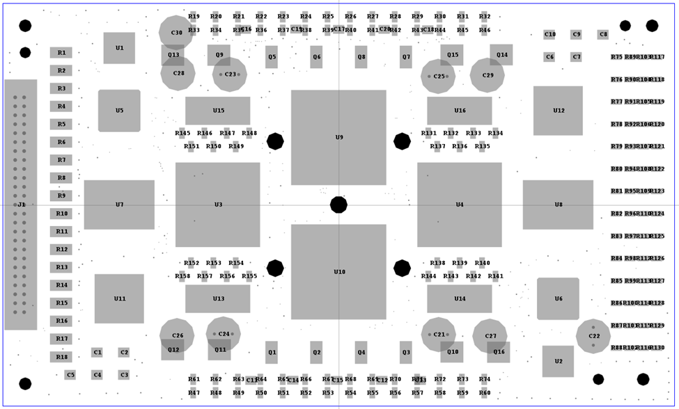
Our earlier analyses indicated harmonic vibration was also causing our board to fail. There was significant displacement in the center that was likely causing our BGA boards to fail. In an attempt to remedy this issue, I have decided to add several mount points to minimize deflection in the center of the board to better secure the BGA packages.
We can see that the natural frequency has increased. This suggests that we are on the right track.
The harmonic vibration results are much better than before, we have no failing components now.
Lets test the other analyses and see if adding additional mount points has negatively impacted our life predictions.
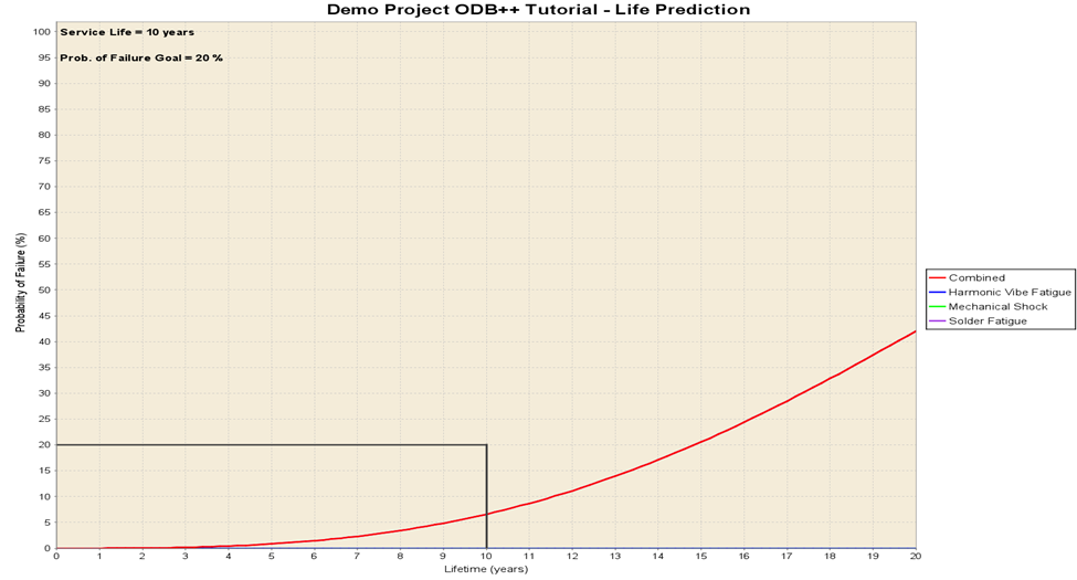
Figure 11: Combined Life Prediction.
It looks like we have brought our board within our specifications. You may be wondering why the random vibration life prediction is not available. When we check the Sherlock warning messages, we get an error that there were no modes extracted and the analysis cannot be conducted. Our load profile frequencies were from 10Hz to 500Hz, and the lowest natural frequency generated was at 819.96Hz.
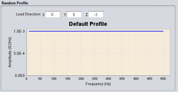
Since there were no mode shapes generated for the frequency range that the Random Vibration took place, no analysis was conducted.
Conclusion
Sherlock is a powerful tool that we can use to quickly analyze PCBs. We can import PCBs, run a variety of analyses, and evaluate which components are likely to impact performance life. We can use those results to quickly iterate and improve our board to meet our design life requirements.
Additional Resources
