
Understanding Antenna Array Analysis: An Introduction to Array Factor Calculations with ANSYS HFSS
Antennas are at the heart of many modern technologies, from wireless communication systems to radar and satellite applications. Designing and optimizing antenna arrays is a critical task for engineers aiming to achieve precise and efficient radiation patterns. But where do you start if you're working with complex antenna arrays? That's where tools like ANSYS HFSS come into play, offering a robust platform for antenna design and analysis.
One key feature of ANSYS HFSS is its array factor calculation method, a powerful technique to approximate finite array patterns based on a single simulated antenna element. By leveraging this capability, engineers can quickly evaluate array performance, saving time and computational resources. However, like any tool, its effectiveness depends on proper use and understanding of its limitations.
Why Use Array Factor Calculations?
Array factor calculations simplify the analysis of antenna arrays by mathematically combining the radiation pattern of a single array element with a user-defined configuration of multiple elements. This approach provides insights into how an antenna array will behave without the need to simulate the entire array physically, which can be computationally expensive.
For engineers exploring array designs, this method is invaluable for:
- Preliminary Design Assessments: Quickly gauge the impact of array configurations like element spacing, taper functions, and scan angles.
- Directivity Optimization: Evaluate improvements in directivity based on element arrangements.
- Concept Validation: Test design concepts before committing to detailed full-array simulations.
Key Considerations When Using Array Factor Calculations
While the array factor method is a powerful tool, it has inherent assumptions that may impact accuracy:
- Element Independence: It assumes all elements are identical and that the radiation pattern of each element is unaffected by its position in the array.
- Neighboring Element Effects: Mutual coupling and edge effects are not accounted for, which may lead to inaccuracies for arrays where these factors are significant.
By understanding these limitations, users can effectively integrate array factor calculations into their workflow, complementing other simulation techniques for a comprehensive analysis.
Getting Started with ANSYS HFSS
In the following sections of this blog, we’ll dive into a practical example, showcasing how to design an antenna element, set up the simulation environment, and utilize the array factor method. Whether you're a seasoned professional or new to antenna design, these insights will help you unlock the full potential of ANSYS HFSS in your projects.
Ready to explore the possibilities? Let’s begin!
Overview
In this blog we will use the ANSYS HFSS built in array factor calculation method to compute antenna array radiation pattern for designs that have analyzed a single array element. In this method, HFSS mathematically calculates the array factor based on the user input and then apply it on the single element simulated far field pattern to get an approximate finite array pattern.
This method is a useful tool for antenna array analysis, however, the analysis can yield incorrect results if used improperly. An HFSS single array element solution does not generally take into account the effects of the element's hypothetical neighbors. It assumes that all elements are identical and the element pattern doesn’t depend on the location in the array, if these impacts are significant then this method will be invalid.
Model Geometry
To begin, users can utilize the intuitive interface to draw the antenna geometry, which can range from simple structures like wire antennas to complex array configurations. In this example, we will utilize the built in Antenna Toolkit to create a simple prob-fed patch antenna.
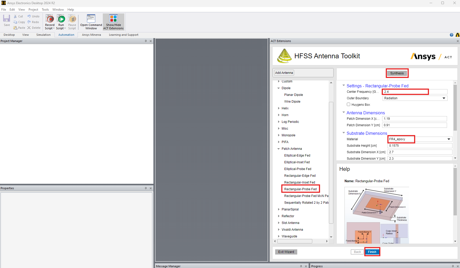
To launch the antenna tool kit, click on "Automation" then click on "Show/Hide Act Extensions". Once the Act extensions appeared, click on "Launch Wizards and select "Antenna Tool kit".
When the antenna toolkit get launched, Select "Rectangular-Probe fed" Patch antenna, change the design frequency to 2.4 GHz, material to FR4_epoxy, click on "Synthesis" then finally click on "Finish"


Antenna Element Setup & Performance
Lattice pairs boundary is used in this example to simulate the single element radiation pattern. These boundaries enable the user to model planes of periodicity, where the E-field on one surface matches the E-field on another to within a phase difference.


Array Factor Calculation Setup
To add the array factor calculation, you can go to the HFSS menu item > Radiation> Antenna Array> Antenna Array Setup. HFSS provides 2 options; 1) Custom Array Setup: where the user can import an array setup using a txt file or 2) Parametric Array Setup: where the user can define the array setup in this interface.

1) Parametric Array Setup
In this setup user can define center position of the array, the direction of the array, the layout type, design frequency, and size and spacing of the array based on physical dimensions or electrical length. In the Array Weight tab, user can select different aperture taper function and different scan conditions.
In this example, a linear array of 4 elements is defined with a spacing of 8.7 cm and uniform taper function for the broadside case.


After the array is defined, we can look at the farfield data and perform diffenet analysis. Below we see the impact on the directivity. As seen, the directivity has increased by 6 dB (a factor of 4) as expected.

2) Custom Array Setup
The second approach to create the array setup is to import a txt file that contains; 1) number of element, position, amplitude, and phase. The text file must have the following format. Coordinate values are assumed to be model units, and phase and amplitude are in SI units (radians and volts respectively):
Nx
x_1 y_1 z_1 A_1 P_1
x_2 y_2 z_2 A_2 P_2
...
...
x_N y_N z_N A_N P_N
where
l x_1 is the x-coordinate position of the first element.
l y_1 is the y-coordinate position of the first element.
l z_1 is the y-coordinate position of the first element.
l A_1 is the amplitude weight of the first element. Amplitude references voltage.
l P_1 is the phase weight for the first element. Phase references radians.
Below is an example of linear array of 4 elements placed along the x-axis similar to the one defined using the "Parametric Array Setup";
4
0 0 0 1 0deg
8.7cm 0 0 1 0deg
17.4cm 0 0 1 0deg
26.1cm 0 0 1 0deg
To create the custom array setup, click on import definition and browse to the txt file. user can click on "View Definition" to view the file as seen below.

A complete demonstration of using the array factor calculation is shown in the video link below:
Downloadable Resources