
Qi wireless charging utilizes inductive charging technology, where power is transferred from a charging station to a compatible device without physical connectors or cables. The Qi standard, governed by the WPC, ensures interoperability between different wireless charging products. Here are the core features of the Qi v1.3 standard:
Key Features of the Qi v1.3 Standard
- Authentication: Ensures that the charging device and the receiver communicate to confirm compatibility and safety before transferring power.
- Compliance Testing Enhancements: Reduces development costs by streamlining the testing process, ensuring products meet high reliability and safety standards.
- Advanced Foreign Object Detection (FOD): Prevents power transfer when a metal object is detected between the charger and the device, enhancing safety by reducing risk of overheating or damage.
The Role of Ansys in Qi Wireless Charging
Ansys Maxwell is a powerful simulation tool for designing and analyzing electromagnetic and electromechanical devices. For Qi wireless charging systems, Maxwell can simulate the electromagnetic behavior of the charging coils, predict the thermal and structural impacts of different designs, and optimize the system for maximum efficiency and safety. You can then integrate Ansys Maxwell’s EM analysis — including EM losses in coils (solid loss, litz winding loss, etc), cores (hysteresis loss), shields, and permanent magnets (induced eddy current loss) — into Ansys Icepak to analyze thermal performance.
Simulation Capabilities:
- Electromagnetic Field Simulation: Maxwell's finite element method (FEM) accurately models the electromagnetic fields generated by the Qi charging coils, allowing for precise design and optimization.
- Thermal Analysis: Integration with Ansys Icepak provides insights into the thermal challenges within the system, helping designers minimize heat-related issues and ensure reliable operation.
- System Efficiency Optimization: Uses reduced order models (ROMs) to predict system performance under various conditions, improving design quality and efficiency.
Simulating Qi Wireless Charging in ANSYS Maxwell
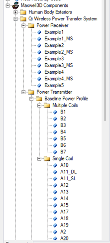
Step 1: Accessing the Qi Wireless Power Transfer System Library
-
Navigating Component Libraries:
- Enable viewing by navigating to
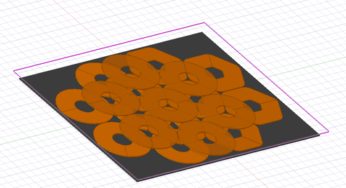
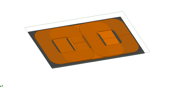
View > Component Libraries. - In the Component Libraries tree, locate the Qi Wireless Power Transfer System models.
- Drag and drop selected models directly into the Modeler window.
- Enable viewing by navigating to
-
Using the 3D Component Library Browser:
- Go to
Draw > 3D Component Library > Browse...to open the component dialog. - Click on
SysLibto view available libraries and select the Qi Wireless Power Transfer System models. - View detailed images and descriptions for each component by selecting them.
- Go to
Step 2: Setting Up the Simulation Model
-
Inserting Components:
- Double-click a model in the Component Libraries window or click
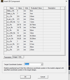
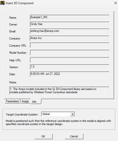
Openin the Browse dialog to see the Insert 3D Component dialog box. - Check the
Parameters,Image, andInfotabs to understand the selected component's specifications and requirements.
- Double-click a model in the Component Libraries window or click
-
Editing Components:
- To customize a component, copy its design file from the
SysLibdirectory to yourPersonalLiborUserLibdirectory. - Open the copied file from your personal library and make the necessary edits.
- To customize a component, copy its design file from the
Additionally, the Qi Wireless Power Transfer System library is accessible via Draw > 3D Component Library > Browse... to open the Browse 3D Component dialog. From there, select SysLib to see the libraries available in your installation.
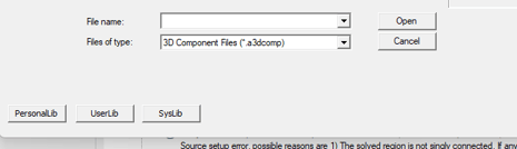
Within this library, you can browse through the Qi Wireless Power Transfer System models and choose from the components available. After selecting a component file, you will be able to view the Image and Info associated with that component.
Step 3: Configuring the Simulation
- Meshing and Material Selection:
- Apply Maxwell’s automatic adaptive meshing for high-quality mesh generation around the coils, ensuring accurate electromagnetic field calculations.
- Choose appropriate magnetic materials for coils and select thermal properties that match the operational conditions.
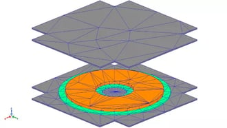
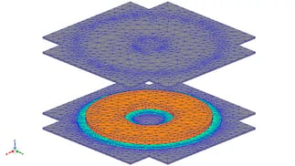
Initial Mesh vs Adaptive Mesh
Step 4: Running and Analyzing the Simulation
- Initial Electromagnetic Analysis:
- Execute the simulation to visualize the magnetic field distribution and identify potential misalignments or inefficiencies.
- Integrated Thermal Analysis:
- Use Ansys Icepak within Maxwell to conduct a thermal analysis, evaluating temperature profiles and ensuring the device operates within safe thermal limits.
- Use Ansys Icepak within Maxwell to conduct a thermal analysis, evaluating temperature profiles and ensuring the device operates within safe thermal limits.
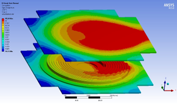
Temperature Distribution
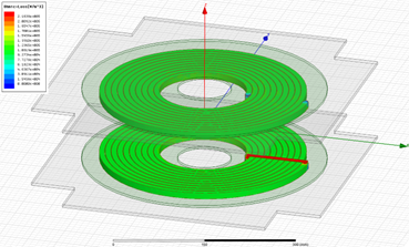
Winding Ohmic Loss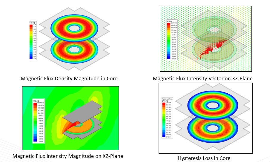
Step 5: Optimizing the Design
- Utilizing Optimization Tools:
- Create reduced order model to explore design sensitivities, optimize parameters, and enhance overall system performance with circuit simulations.
- Create reduced order model to explore design sensitivities, optimize parameters, and enhance overall system performance with circuit simulations.
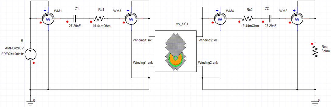
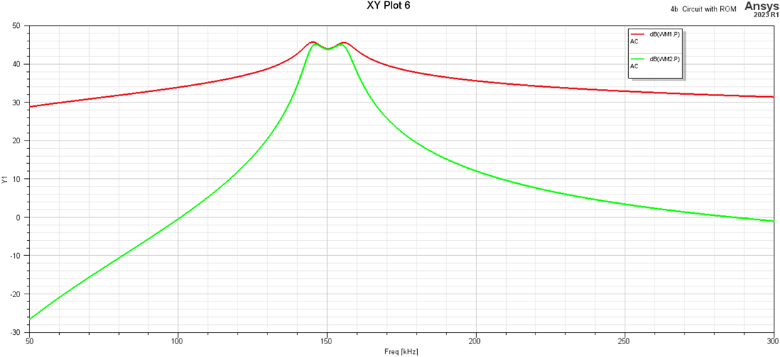
Bode Plot of Input Impedance
Further Analysis and Optimization with Ansys optiSLang and Ansys Icepak
After completing the initial electromagnetic and thermal analyses in Ansys Maxwell, the next step involves enhancing the design and performance predictions using Ansys optiSLang and Ansys Icepak. These tools provide deep insights into the design variables and thermal performance, respectively, enabling a more comprehensive optimization of the Qi wireless charging system.
Conclusion
Simulating Qi wireless charging systems with ANSYS Maxwell offers designers the tools to innovate and optimize with precision. By following the detailed steps outlined above, engineers can develop safer, more efficient wireless charging solutions that comply with the latest Qi standards. The Qi v1.3 enhancements focus on improving safety and user experience, making it a significant upgrade for future wireless charging technologies