
Being able to change the friction coefficient of a contact may be needed during special instances within an analysis. Some applications where this may be important could be due to particulate accumulation on a surface due to wear, uneven lubrication or due to thermal effects. While the mechanical GUI does not have this feature directly, we can apply a command object to a frictional contact to adjust the friction coefficient based on a specified criteria. The case below walks through an example of changing the friction coefficient due to the sliding distance of a block on a plane.

In this example, we are going to adjust the friction coefficient between the two objects as it slides across the surface through the use of the TB, TBFIELD, and TBDATA commands within MAPDL. To demonstrate the effect we will use the following friction coefficient adjustments based on the sliding distance of the block.
| Sliding Distance (mm) | Friction Coefficient |
| 0 | 0.1 |
| 2 | 0.3 |
| 4 | 0 |
| 5 | 0.6 |
To do this, we begin by creating a frictional contact between the two bodies. The friction coefficient applied at this point is irrelevant as it will be removed during the command operation.

From this point, we can insert a command by right clicking on the frictional contact navigating to Insert and then selecting Commands.

This will allow us to add APDL code to the contact and adjust the friction coefficient based on sliding distance. The code below walks through the code to apply the friction coefficient table from earlier.
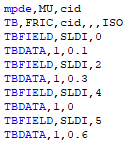
The first line in the code deletes the existing friction coefficient data. The use of "cid" identifies the contact that houses the command object. The second line of code sets up a data table for friction for the contact. It also specifies that the properties are isometric (ISO). The following lines are filling in the active data table. Each row of the table requires two lines to populate. TBFIELD specifies two items. The first item is the change condition. In this case SLDI indicates that the absolute total sliding distance will be used to determine the friction coefficient. The second item states it will set the data values at a 0 sliding distance. TBDATA is specifying the friction coefficient related to the recent TBFIELD command. Which for the 0 sliding distance is 0.1. This is repeated until the full table is populated.
There are a few things to note with this table. The first is that ANSYS will linearly interpolate values between field data for use. This means that if one wishes to keep the friction coefficient at 0.1 between a sliding distance of 0 and 2 then an additional condition will be needed to control the interpolation. This usually means adding a sliding distance of 1.99 that correlates to a friction coefficient of 0.1. The second item to note is that these distances will be interpreted in the solved unit system. This means if the sliding distances are entered using meters and the system is solved using inches, then the friction coefficient will be adjusted based on inches.
Now that the command has been entered, we can setup some load cases. The plate is fixed and the block will experience 4 load cases. The first load case applies a 10N downward force to apply pressure between the block and plate. The final three load cases will each apply a 2mm displacement along the x-direction for a total displacement of 6mm.

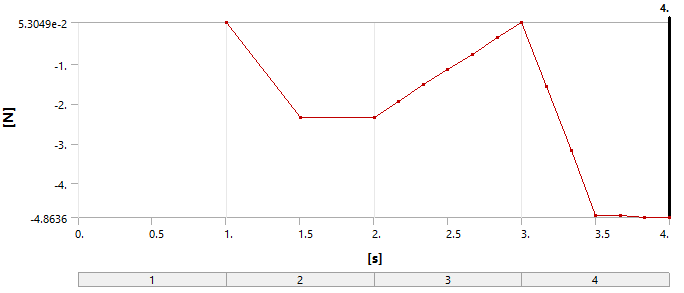
After solving, the following reaction plot indicates negative reaction that is changing during the load steps.
Charting the reaction with the applied displacement shows reaction changes that are expected with the above table's changing friction coefficient.
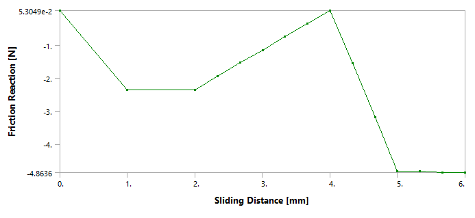
These graphs even indicate a return to near zero reaction when we set the friction coefficient to be 0. It also shows the linear interpolative behavior of how ANSYS approaches the material property data table.
Other methods to control the frictional coefficient such as time, sliding velocity and temperature are also available to use within the TBFIELD command. A list of all available field variables that can be used is found within the ANSYS documentation for TBFIELD.
