
Learn how to determine relative humidity in your CFD model.
Understanding Relative Humidity
Atmospheric air is the mixture of dry air and water vapor, each one has a pressure that combined is equal to the vapor pressure. Relative humidity refers to the amount of moisture in the air compared to the maximum amount of moisture the air can hold at a specific temperature. It is usually expressed as a percentage. It ranges from 0 (dry air) to 100 percent (saturated air). The expression below shows the relation between the vapor pressure (Pv) and the saturation pressure (Psat), which is the partial pressure of water vapor in saturated air,
Where f is the relative humidity. The saturation pressure is available in different sources in Literature. Understanding relative humidity is crucial in various applications, such as weather forecasting, HVAC systems (Comfort), and indoor air quality management. For instance, in cooler temperatures, the air has a reduced ability to hold moisture, causing water to more readily condense and separate from the air.
Calculation
The main goal is to calculate the mass fraction of water vapor needed for the boundary conditions in the CFD model. Note that there is a specific mass fraction for a given air temperature and relative humidity. Ultimately, these equations need to be created in CFD-Post as expressions, as explained in the video in the following section. Please follow these steps:
- Find the saturation pressure. While tables are available in books, in this case, the Tetens equation is used for this purpose (Monteith, J.L., and Unsworth, M.H. 2008. Principles of Environmental Physics. Third Ed. AP, Amsterdam). The pressure is given in Pascals.
- Since the relative humidity f is a known value, the equation presented in the previous section is used to determine the vapor pressure (or partial pressure, Pp). Next, identify your absolute pressure (Pabs) and iteratively calculate the Mixing Ratio (MR) using the following equation,
![]()
- Finally, determine the Mass Fraction (MFw) of the water vapor iteratively using the following equation,
How to set up your CFD model
For this demonstration the flow from two chimneys is modeled in a steady-state using Ansys CFX. Atmospheric air is also included, flowing in the positive direction of the Y-axis as shown in the image below. Both the air and that from the chimneys have specified velocity, temperature, and relative humidity. This means, the model handles Species transport.
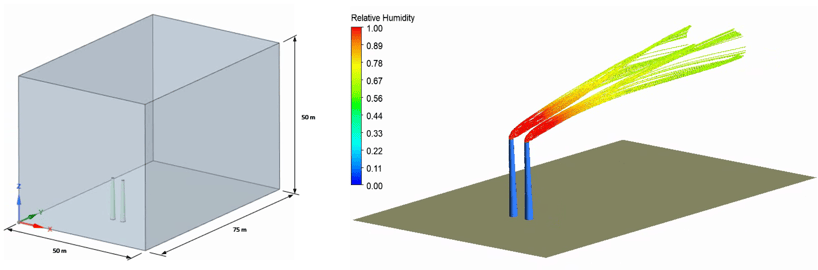 Fluid domain and Streamlines colored by Relative Humidity
The geometry is created in Ansys SpaceClaim, and the mesh is created in Ansys Meshing using tetrahedral elements within Workbench. The extents of the fluid domain were chosen arbitrarily and can be adjusted accordingly. The equations mentioned earlier must be included in CFD-Post to visualize the results and the following video shows the procedure to get the results.