
Abstract:
Dies are very often used in electronics industries. Understanding the parasitic characteristic of its leads are important for designers. Q3D is the prefect tool to calculate RLCG. It can be used in high speed boards or low frequency power electronics.
In video below, we showed how to modify geometry, set up the model, and check the results.
Details:
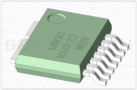
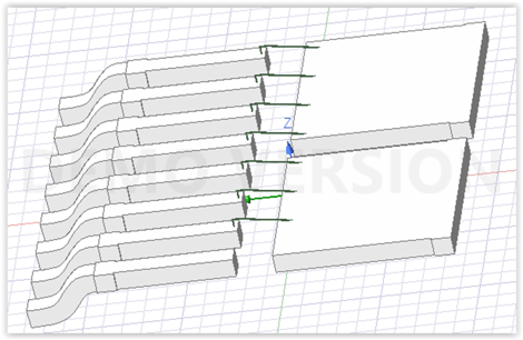
A geometry can be created in Q3D or imported as different CAD formats. In this example, we will have one die with three leads and one with four leads once the geometry is modified.
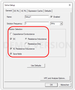
Next, we set up the solution.
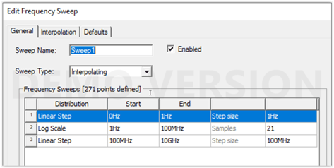
Then we add the sweep since we would like to see R and L in different frequency
Once model is solved, we can see the result. Results that are shown here are AC-R, AC-L, DC-R, DC-L.
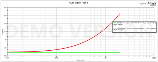
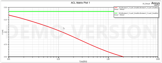
As you can see from the results, Q3D can compute the high-frequency (AC) resistance and inductance. It assumes well-developed skin effect and solves for the current distribution on the conductor surfaces.
The DC resistance is a constant while the AC resistance varies with frequency according to the skin depth.
As mentioned above and shown in video below, it is recommended to compute both the DC and AC RL parameters and add a frequency sweep so that the blended solution can be obtained. Blended solution automatically take care of the skin effect, hence consider resistance and inductance result as a function of frequency with accurate result. If sweep frequency and both DC and AC are not chosen, Q3D still solve the model however it would be more accurate if former approach is used.