
In the last two CFD posts, we talk about the role of CFD in the Bioprocessing industry. We emphasized the importance that mixing has on the bioreactor´s performance. Today, we will turn 180°, and we will talk about the importance of separation processes in different industries and, particularly, on the role of CFD in modeling such processes.
Before starting, it is important to recap some basic definitions regarding the separation process. One of the main concepts that any engineer, physician, scientist, or person that works with separation processes must know is the concept of phase. Here, it is essential to note that this definition can be understood in two different ways; the first is the physical way, which says that “A phase, or state of matter, is a domain within a many-body system within which relevant physical properties are uniform. Relevant properties may include chemical composition, stoichiometry, and density, which do not reflect how the components are arranged in space” [1]. The three main phases or states of matter are: i) solid, ii) liquid, and iii) gas. The second one is the CFD way, which states that a phase is any material that forms an interface with another materials. Regarding the last definition, a stratified mixture of oil and water is considered as a two-phase flow, even when both materials are liquids. Some examples of multiphase flows from the CFD perspective are:
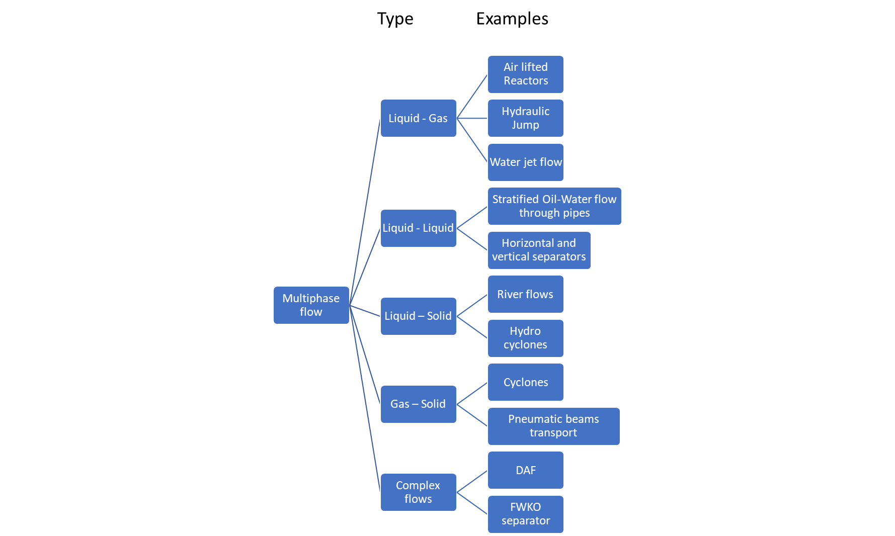
Figure 1- Examples of multiphase flows
All these applications are widespread in different industries. CFD plays a significant role in its design and performance improvement. However, talking about all this applications would be very extensive. For this reasons, we will create a series of blogs focusing on separation processes and applications.
As a starting point, we will begin with this blog talking about a solid-gas separating application, and particularly, we will talk about the cyclone separator.
The cyclone
The cyclone is a mechanical collector whose primary function is to separate solid particles from a gas using centrifugal force [2]. This particulate matter collection equipment is the most used device in all industrial areas (energy, chemical, and cement, among others) because its simple design is absent of moving parts, which results in low maintenance costs [3]. The cyclone operation can be summarized as follows:
-
The gas is tangentially entering the cyclone.
-
The gas descends in a spiral pattern toward the bottom of the cone because of the cyclone geometry.
-
The particles are separated from the gas and moves towards the cyclone walls. At the walls, the particles strike and lost kinetic energy. Therefore, the particles fall to the bottom of the conical section.
-
Finally, the gas rises through a second spiral. This spiral has a smaller diameter than the initial spiral. The gas exits the top of the cyclone through a vertical duct known as the vortex finder.
Even though the cyclone operation looks straightforward, the design of this equipment is not an easy task. The main goals of a good cyclone design are related to the separation efficiency and the pressure drop. Hence, having a higher separation efficiency with a lower pressure drop is the most desired output for every cyclone design. To this effect, different physical and geometrical variables directly affect the cyclone behaviour. Some of these variables are the density of the particles, the viscosity of the gas, the geometrical dimensions of the cyclone, the cut-off diameter of the particles, the inlet velocity, among others [3]. For instance, the cyclone performance is controlled by many variables, which makes this process very difficult for doing it manually and very expensive for doing lab tests. For this reason, in recent years, CFD has become an essential tool for doing cyclone designs [2-4].
According to our experience in simulation and modeling of cyclone separators, we have found that the common issues that CFD engineers face in the development of Cyclone CFD models are presented in the following tasks:
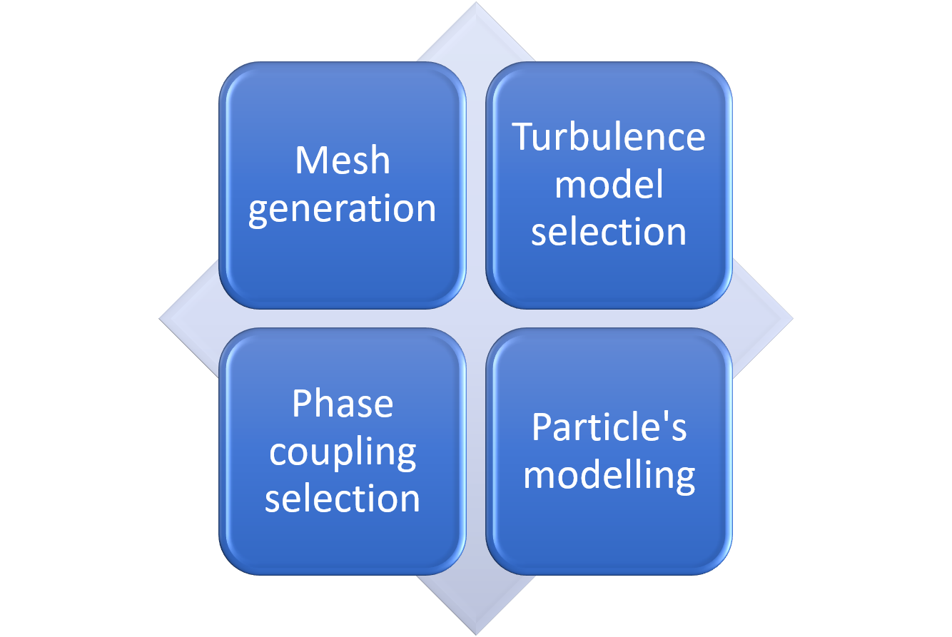
Figure 2. Tasks that generate major problems on cyclone CFD modeling
This part of the blog will talk only about some tips for creating a good mesh and selecting the appropriate turbulence model. The particle´s modeling and the phase coupling will be discussed in the next part of this blog.
Mesh: In fluid dynamics applications, it is the most desirable to use hexahedral (HEX) meshes. This type of mesh is characterized by low numerical diffusion, particularly in flow perpendicular to the faces of control volumes. Unfortunately, obtaining Hex meshes is not an easy task for many geometries, leading to a very time-consuming step in the CFD analysis. In fact, for industrial applications around 50% of the time consumed for numerical simulation is required for meshing tasks [5]. Nevertheless, many studies have demonstrated that for obtaining an accurate cyclone CFD model, it is necessary to use Hex meshes [2] [3] [5], even when some recent studies have evaluated the feasibility of using Poly meshes for this application [6]; for these reasons, developing Cyclone CFD models requires dedication for building a good mesh. If you want to know more about how to make a Hex mesh for a cyclone, you can check the following video
In Figure 3, it is observed the difference between a HEX mesh and a Poly mesh. In ANSYS Fluids, It is more complicated to build a Hex mesh; however, the Hex mesh is the most common mesh found in research activities (References). The latter is a consequence of the proven accuracy of the results obtained with a Hex mesh. Nevertheless, it is essential to remark that no matter the type of mesh you use, you always need to do a mesh independence study and validate your model to have confidence.
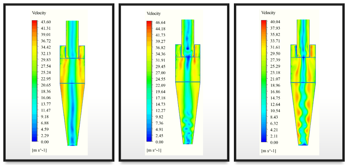
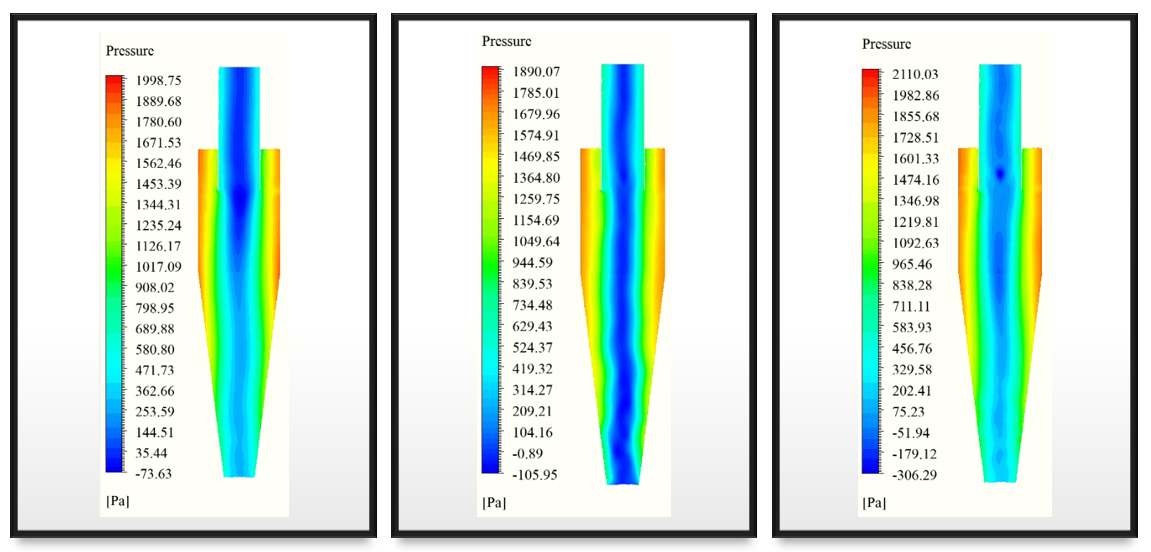
Figures 4 and 5 compare the results obtained with a Hex mesh and a Poly mesh for the same conditions. It is observed that the mesh have an important influence over the results, and particularly, according to previous reasearch studies, the Hex mesh give more accurate results than the other type of meshes for cyclone modeling purposes.
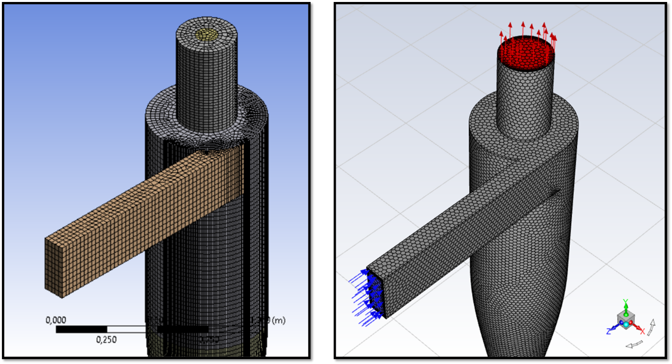
Figure 3. Left: Hex mesh, Right: Poly mesh
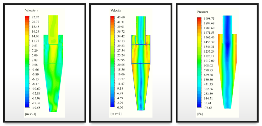
Figure 4. Results obtained with a Hex mesh. Left) Axial velocity, Center) Velocity magnitude, Right) Static pressure
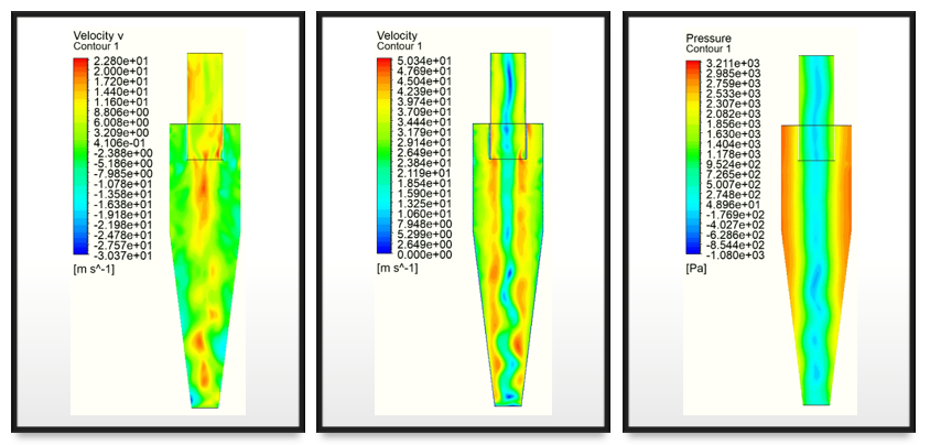
Figure 5. Results obtained with a Poly mesh. Left) Axial velocity, Center) Velocity magnitude, Right) Static pressure
Turbulence modeling: In CFD, the choice of a turbulence model mainly depends on:
-
The nature of the flow.
-
The available hardware resources.
-
The proven ability of the model to catch the physics of the fluid flow.
The turbulence models can be classified in:
-
RANS models
-
LES models
-
DES models
-
SAS models
-
DNS, which is not a turbulence model classification
ANSYS Fluent gives different alternatives for turbulence modeling. For example, to model the Reynolds stresses in RANS equations, Fluent provides various closure models: Spalart–Allmaras (SA), k–ε, k–ω, and Reynolds stress model (RSM) models. Also, it gives the option of using more accurate models, such as adaptive simulations (SAS), detached eddy simulations (DES), and large eddy simulations (LES). However, the RANS models are the most used for industrial purposes because of their lower computational cost and enough accuracy for this type of application.
Regarding the RANS models, the SA model is used for external flows such as aerodynamics problems. On the other hand, the k–ε and k–ω models are suitable for most engineering and industrial flows; however, they are formulated based on isotropic eddy-viscosity hypothesis; for instance, both models are not ideal for cyclonic flows [7]. Finally, the RSM model solves the Reynolds stress components together with the dissipation rate. The RSM model considers high streamline curvatures and rapid changes in strains and anisotropy [2] [4]. For instance, the RSM model has already tested cyclonic flows and has reported accurate results [5] [8] [9].
If you want to know more about how to set-up the turbulence models for a cyclone using ANSYS Fluent, look at the following video
Figures 6, 7, and 8 show the results obtained with the RSM, k–ε and k–ω RANS turbulence models. In these figures, it is observed that the results change depending on the turbulence model used. This is because of the nature of the turbulence models, as was mentioned above. Regarding the available literature, the RSM model is the recommended turbulence model for modeling cyclones. However, this is just one of the elements that affect the model's accuracy. For instance, choosing an appropriate turbulence model does not guarantee good model behavior.
Conclusion
The CFD modeling process for a cyclone must be carefully done because of the complex flow field formed. From the geometry construction, through the mesh generation, and finally, the physical model selection, all these processes need a good understanding of the phenomenon and know-how to build an accurate model that can be used for prediction purposes precisely.
This blog aims to give a more in deep insight on how to go about CFD modeling of a cyclone. Some tips were shown, as well as some explicative videos. For more information about this topic, you can contact us.
Finally, a continuation of this blog will be published soon. In the next part, we discuss the modeling of the particles, including the phases coupling.
Bibliography
[1] D. Grier, «Re: Anybody knows a good definition of "phase"?,» 5 November 2012. [En línea]. Available: https://www.researchgate.net/post/Anybody-knows-a-good-definition-of-phase/5097ec2ae24a46d16e000061/citation/download. [Último acceso: 20 May 2021].
[2] L. Brar, L. Sharma y K. Elsayed, «The effect of the cyclone length on the performance of Stairmand high-efficiency,» Powder Technology, vol. 286, pp. 668-677, 2015.
[3] C. Zabala-Quintero, J. Ramirez-Pastran y M. J. Torres, «Performance characterization of a new model for a cyclone separator of particles using Computational Fluid Dynamics,» Applied Sciences, p. 21, 2021.
[4] O. Hamdy, M. Bassily, H. El-batsh y T. Mekhail, «Numerical study of the effect of changing the cyclon cone length on the gas flow field,» Applied mathematical modelling, vol. 46, pp. 81-97, 2017.
[5] L. Brar , R. Sharma y R. Dwivedi, «Effect of Vortex Finder Diameter on Flow Field and Collection Efficiency of Cyclone Separators,» Particulate Science and Technology, vol. 33, nº 1, pp. 34-40, 2015.
[6] J. Houben, C. Weiss, E. Brunnmair y S. Pirker, «CFD Simulations of Pressure Drop and Velocity Field in a Cyclone Separator with Central Vortex Stabilization Rod,» Journal of Applied Fluid Mechanics, vol. 9, nº 1, pp. 487-499, 2016.
[7] B. Wang, D. Xu, K. Chu y A. Yu, «Numerical study of gas – solid flow in a cyclone separator,» Applied Mathematical Modelling, vol. 30, pp. 1326-1342, 2066.
[8] M. B. L. S. &. L. G. Wasilewski, «Experimental and numerical investigation on the performance of square cyclones with different vortex finder configurations,» Separation and Purification Technology, vol. 239, 2020.
[9] K. E. a. C. Lacor, «The effect of cyclone inlet dimensions on the flow pattern and performance,» Applied Mathematical Modelling, vol. 35, nº 4, pp. 1952-1968, 2011.