
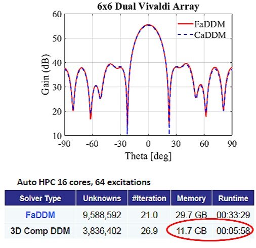
Last year, as ANSYS has published Design Base Station Antenna Arrays for 5G Wireless Network, it introduces a simulation workflow using ANSYS HFSS to tackle problems related to the antenna’s beamforming capabilities that use multiple-input-multiple-output (MIMO) techniques. Finite array domain decomposition method (FADDM) is also mentioned in the paper, this is a solver technique offered in HFSS to solve large-scale array problems by making optimum use of the memory and CPU.
In this article, we are going to introduced the latest updates of finite array simulation technique — 3D Component Array Domain Decomposition Method (3DCA-DDM). This new technique enables engineers to model finite (semi-)periodic structures which contains non-identical unit cells. At the same time, it helps to speed up simulation time with memory usage reduction compared to simulating the FADDM or explicit array.
Antenna array and the future
Massive MIMO is the key technique in 5G communication system, the concept is to increase the number of antennas in an array (64, 128 or more) in the base station to achieve a larger channel capacity. In phased array radar applications, the number of antennas can go up to hundreds, and thousands of elements in an array.
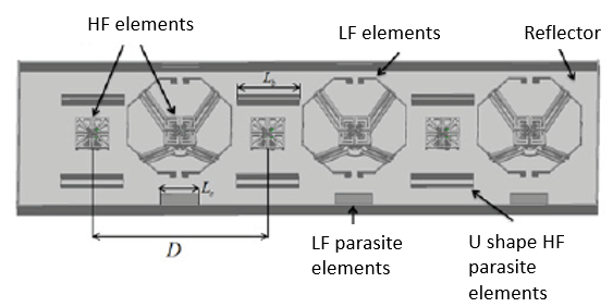
Today, 5G wireless systems are getting smaller and more compact, this means there will be many antenna array elements fitting into a small device. For examples, base stations are designed to have multiple frequency bands, and the antenna array design due to the high and low frequency elements.
Question: Is there a method to simulate antenna array structure with non-identical unit cells?
Answer: Yes, 3D component array domain decomposition method in ANSYS HFSS! It’s as accurate as simulating the explicit model, but with less time and memories!
3D component array domain decomposition method
3DCA-DDM is a breakthrough and new feature introduced in ANSYS HFSS 2019R3 for modeling finite (semi-)periodic structures which contains non-identical unit cells.
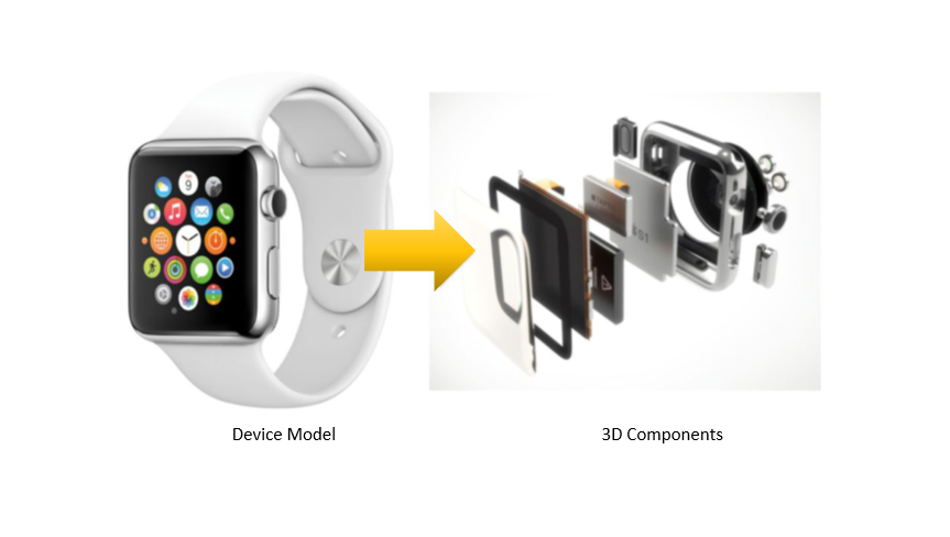
1. What is 3d component?
3D component is an independent ANSYS HFSS model, it can be created and integrated into a larger assemblies. A 3D component model contains all relevant information: geometry, materials, boundary conditions, design parameters and ports (when necessary), for inclusion in a fully coupled, 3D electromagnetic simulation.
In addition, a patented encryption technology allows component providers to hide and protect critical intellectual property (IP), while fully describing their parts for downstream simulation.
2. 3D Component array
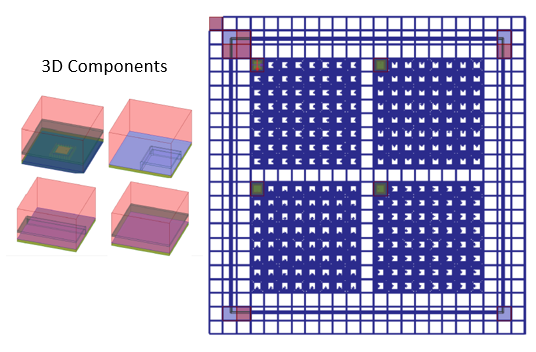
The overall workflow starts with creating the 3D components representing different unit cells in the model, then these 3D components can be placed into an array structure to create the model. The benefits of using 3D components is to adapt the component mesh independently, and reduce the overall model rendering and meshing size. With a single 3D component meshing, we can duplicate and use it for all other repeating structures in the array.
To utilize the new 3D Component Finite Array workflow with non-identical unit cells, the unit cells must meet the following requirements:
-
Unit cells are defined as 3D Components.
-
Dimensions of unit cells’ bounding boxes are identical.
-
Appropriate Lattice Pairs are defined on surfaces of unit cells
Now, we are going to check out the example below
Example
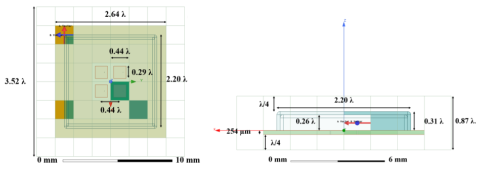
This example presents a 77 GHz 2x2 phased array antenna and radome integration by using the 3D component finite array workflow.
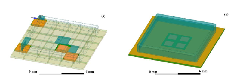
a) 3DCA-DDM, (b) Explicit Array.
Simulation Time: 3 minutes and 16 secs, RAM: under 8.53GB in (4-core with 64 GB RAM machine and auto HPC settings).
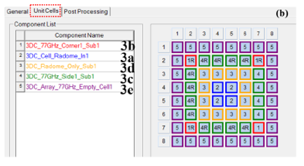
We start with creating the 3D components to represent different unit cells in the model; then insert the components into HFSS design, and create the array similar to creating Finite Array from a unit cell. See following image,
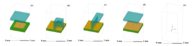
3D components unit cells used in this workflow. (a) Patch antenna, (b) Radome corner and substrate, (c) Radome side and substrate, (d) Top radome and substrate, (e) Empty unit cell.
Then we will use the following matrix to arrange the unit cells to create the array
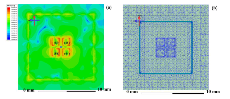
After creating the 3D component array model, we can start the simulation. In the 3DCA-DDM simulation, HFSS creates non-conformal mesh interfaces between each 3D component unit cells, which reduces the memory footprint and improves the simulation performance. Figures below shows the complex magnitude of the E field and meshing of the model,
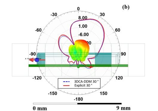
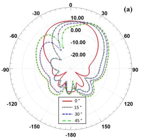
Peak realized gain rectangular plot at different Scan Angle Theta (0°,15°, 30° and 45°) for the 3DCA-DDM. Overlay representation of the peak realized gain 3D polar plot and radiation pattern at phi=0° cut with Scan Angle Theta in 30°, note that the beam has been steered at 30°, note also the comparison between the 3DCA-DDM and explicit array results.
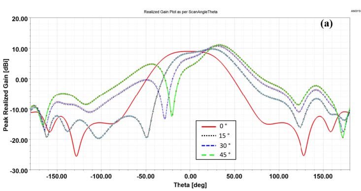
The peak realized gain radiation pattern for different Scan Angle Theta at (0°,15°, 30° and 45°), in the phi=0° cut, and phi=90° cut, respectively.
 <div
<div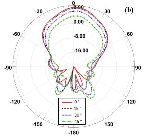
Reference
-
M. Commens and K. Zhao, "Finite antenna array analysis with a unit-cell domain decomposition method," 2012 42nd European Microwave Conference, Amsterdam, Netherlands, 2012, pp. 313-316, doi: 10.23919/EuMC.2012.6459417.
-
“How to Design Base Station (or Microcell) Antenna Arrays for 5G Wireless Networks,” ANSYS lnc
-
“77 GHz 2x2 Phased Array Antenna and Radome based on the 3D Component Finite Array Workflow,” ANSYS lnc