
Introduction
Metal additive manufacturing (AM) offers unparalleled design freedom and performance potential. However, ensuring that a part prints successfully the first time remains a significant challenge. Warping, recoater blade crashes, and excessive residual stresses can quickly turn a promising build into scrap.
Ansys Additive Print bridges this gap by allowing engineers and machine operators to virtually simulate the build process before a single layer is printed. The tool predicts distortion trends, optimizes support strategies, and helps achieve “first-time-right” builds — minimizing costly trial-and-error on the machine.
Why Additive Print Matters.
During metal AM, each layer’s rapid heating and cooling generates thermal stresses that can lead to part distortion, delamination, or support failure. Supports are critical to anchor the part to the base plate and resist these accumulated stresses until stress relief or cut-off.
However, excessive supports increase post-processing costs and risk damaging finished surfaces. Iterating support designs directly on the machine is not only time-consuming but also expensive. Additive Print enables engineers to understand these in-build distortions virtually, test various orientations, and evaluate support strategies before manufacturing.
Key outcomes include:
- Visualization of stress and deformation during the build.
- Prediction of blade crashes or recoater interference.
- Generation of distortion-compensated STL files.
- Insight into post-cutoff deformation and residual stress behavior.
Simulation Methods: From Simplified to Detailed.
Additive Print offers three main simulation approaches, each balancing speed and accuracy:
Assumed Strain – A fast, simplified method applying uniform strain across the build volume. Ideal for quick distortion predictions but tends to overestimate stresses. Available in Linear Elastic and J2 Plasticity modes.
Scan Pattern – Incorporates anisotropic strain behavior based on scan vectors, offering greater fidelity when local scan orientations significantly affect distortion.
Thermal Strain – The most detailed approach, simulating actual heating and cooling of each voxel as the laser scans. It accounts for multiple reheating cycles, heat-affected zones, and true process parameters such as power, hatch spacing, and scan speed.
While Thermal Strain provides the most accurate results, it requires longer computation times and detailed machine inputs. Engineers typically begin with Assumed Strain for fast iteration, then refine using Scan Pattern or Thermal Strain simulations as needed.
Support Optimization and Control
Support structures in AM are more than simple anchors—they directly influence build success, part accuracy, and post-processing effort. Additive Print offers flexible options:
- Automatic generation of stress-based supports.
- Import of custom STL or grouped support files.
- Direct reading of supports from machine build files.
Users can define parameters such as minimum overhang angle, support height, and support factor of safety (SFS). The SFS controls the strength and density of optimized supports, while thick-wall supports offer higher stiffness but are harder to remove.
The Additive Print Workflow
The workflow is the backbone of Additive Print and the key to unlocking its full potential. It provides a structured, repeatable process for setting up, analyzing, and refining AM builds.
1. Design and Orientation
Start by designing your part in CAD and defining its build orientation in AM setup software. Consider the number, placement, and accessibility of supports early in the process. Once satisfied, export the model in its intended build position to Additive Print.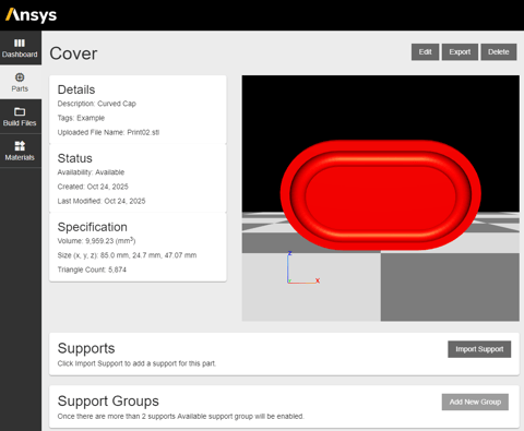
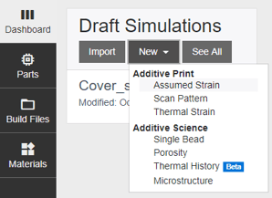
2. Simulation Setup
Within Additive Print, create a new draft simulation and choose the appropriate analysis type — Assumed Strain, Scan Pattern, or Thermal Strain.
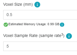
Input the desired voxel size (default 0.5 mm). Voxel Size defines the cubic elements used to divide the part geometry for simulation, affecting accuracy and computational cost. Voxel Sample Rate controls how many subvoxels represent each voxel, improving geometry fidelity for small features. Together, they balance simulation precision and performance.
If required, enable “Simulate with Supports” to allow the software to calculate optimized thin- and thick-wall supports. Each parameter (support yield strength ratio, wall thickness, spacing, etc.) directly affects build integrity and computational time. Minimum Overhang Angle defines the steepest angle below which part surfaces require supports to prevent sagging or distortion during printing. Minimum Support Height sets the vertical distance between the build platform and the lowest point of the part that needs support, ensuring stability while facilitating part removal.
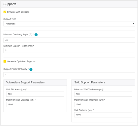
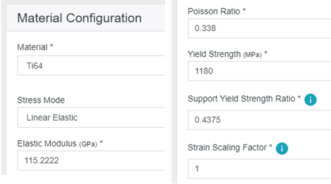
Select the material configuration, and the stress mode. Support Yield Strength Ratio defines the relative strength of support structures compared to the part material, controlling how robust supports are to resist deformation during the build. Strain Scaling Factor (SSF) adjusts the applied strain in simulations to match experimental observations, calibrating distortion predictions for more accurate results.
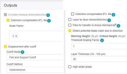
Additive Print also detects blade crash risks, critical strain regions, and post-cutoff deformation. Here the Layer Thickness is the height of each printed layer, directly affecting build resolution and vertical distortion. Threshold Scaling Factor adjusts the sensitivity of blade crash detection in relation to part deformation. Warning Height and Critical Height define the Z-axis distortion limits above which a blade crash is flagged as a potential or likely failure, respectively. Together, these parameters help predict and prevent recoater interference during the build.
3. Run the Simulation
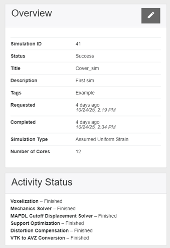
Once parameters are defined, start the simulation. Only one job can run at a time, but progress is tracked in the Simulation Overview, including logs, material data, and output file generation.
4. Review and Analyze Results
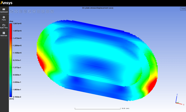
After completion, review deformation and stress predictions directly within Additive Print or export data for advanced post-processing in Ansys Mechanical. Output files may include:
- VTK or AVZ files – for stress and distortion visualization.
- STL compensated geometry – reverse-distorted file for improved dimensional accuracy.
- CSV files – tabular output for quantitative review.
5. Refine and Iterate
The results guide refinement: reorienting the part, modifying support structures, or introducing stiffening geometry. Duplicate existing simulations to vary parameters without starting from scratch. Once a setup yields acceptable distortion and stress results, export the compensated STL and proceed to physical printing.
6. Build and Validate
Finally, the optimized build setup is transferred to the AM machine. The strong correlation between simulated and real-world distortion drastically improves the likelihood of success on the first attempt—reducing wasted material, time, and cost.
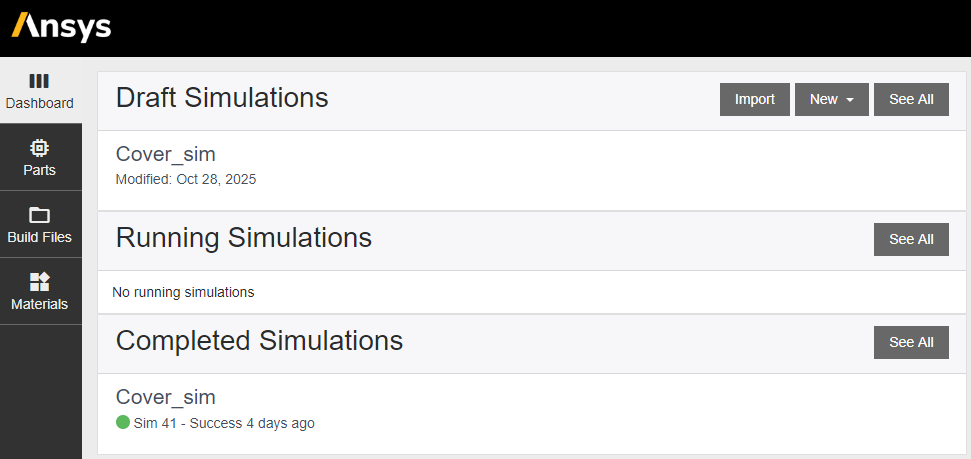
Results and Data Management
Completed simulations can be accessed from the dashboard for review, duplication, or export. Each case stores material configurations, simulation parameters, and output data—ideal for traceability and process documentation. Engineers can export results for further analysis, create comparison studies, or share validated configurations across teams.
To maintain efficiency, it’s recommended to delete completed cases once results are archived, freeing memory and storage.
Conclusion
Ansys Additive Print transforms additive manufacturing from a trial-and-error process into a data-driven engineering workflow. By predicting part distortion, optimizing supports, and providing validated compensation strategies, it enables engineers to achieve first-time build success with confidence.
From conceptual design to final build, the software integrates seamlessly into the additive workflow—turning simulation into a practical tool for every AM engineer. The result: shorter development cycles, reduced costs, and higher-quality printed parts.
Related content
For more details, visit the Youtube video.
Ozen Engineering Expertise

Ozen Engineering Inc. leverages it's extensive consulting expertise in CFD, FEA, thermal, optics, photonics, and electromagnetic simulations to achieve exceptional results across various engineering projects, addressing complex challenges like multiphase flows, erosion modeling, and channel flows using Ansys software.
We provide expert consulting, mentoring, and training to optimize hydraulic and water control systems. Our team leverages advanced simulation tools like Ansys Fluent to deliver precise, reliable solutions for piezoelectric actuator design and analysis. For details, visit https://ozeninc.com.