
Discover the power of ANSYS Motion in simulating robot arm assembly dynamics and optimizing its performance.
Understanding ANSYS Motion And Its Capabilities
ANSYS Motion is a robust simulation software that empowers engineers to analyze and predict the behavior of mechanical systems, including robot arms. By utilizing ANSYS Motion, engineers can simulate the motion and dynamics of robot arms, gaining a comprehensive understanding of how the arm moves and responds in different conditions.
A key strength of ANSYS Motion lies in its accurate modeling and simulation of the intricate interactions between various components of a robot arm, such as joints, links, and actuators. This capability enables engineers to assess the arm's performance and identify any potential areas for improvement or issues.
Moreover, ANSYS Motion provides a wide range of analysis tools and features that allow engineers to investigate the impact of different factors on the performance of a robot arm. This includes examining the effects of various control strategies, optimizing the arm's trajectory, and evaluating its stability and safety.
Our robotic arms are purposefully designed to effortlessly manipulate objects using linear actuators connected to blocks positioned on rails. This innovative design enables the arms to seamlessly manipulate objects through a combination of block movements. In this demonstration, the arm will demonstrate its capability by carrying an 85 kg mass.
Designing and building a robot arm model in ANSYS Motion
Creating a robot arm model in ANSYS Motion requires a step-by-step process. Firstly, engineers must gather essential information about the arm, such as its dimensions, materials, and mechanical components. This data serves as the foundation for developing an accurate 3D model using ANSYS 3D Design tools.
After creating the 3D model, engineers have the ability to specify the arm's kinematic structure, determining the quantity and type of joints and connections, as well as the range of motion for each joint. This enables ANSYS Motion to precisely simulate the arm's motion and dynamics.
To simulate the tripteron, we utilize one fixed joint to securely hold the rail in place. Additionally, there are three translational joints that enable the robotic arm to move, as well as six revolute joints that establish connections between the arms and the entire system, mimicking bearings. Refer to Figure 1 for a visual representation of this setup.
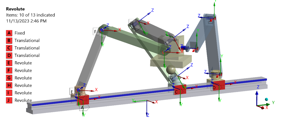
Figure 1: Joint Definitions Of The Robotic System
Next, engineers need to define the arm's actuators, such as motors or hydraulic systems, and their corresponding control strategies. This enables ANSYS Motion to simulate the arm's actuation and response to control inputs.
As shown figure 2 we have function expressions that defines movements of each block so that we can control the object in cartesian space.
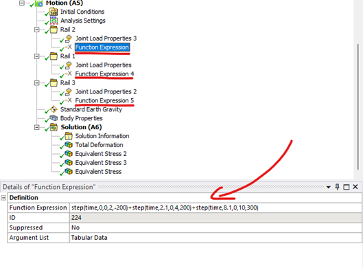
Figure 2: Function Expression Definition
Moreover, the model also includes a body property object, as shown in figure 3. This feature provided by ANSYS Motion allows for faster simulations compared to regular solvers. By changing the definition of the body to from nodal body to modal body, the solver can perform modal analysis for the specific bodies it is scoped to. This efficient multibody dynamics analysis utilizes stiffness information to accurately calculate stress and strains on the bodies.
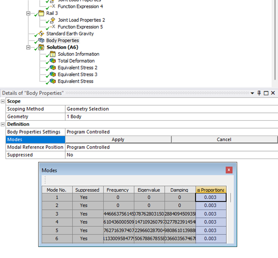
Figure 3: Body Property Object Definition
Once the arm's kinematic structure and actuators are defined, engineers can conduct simulations in ANSYS Motion to thoroughly analyze the arm's performance. This analysis encompasses the assessment of its motion, forces, torques, and other dynamic parameters in various operational scenarios.
The stress, strain, and deformation results can be plotted in the time domain, as demonstrated in Animation 1 below, to optimize the performance of the robotic arms.
Animation 1: Stress Result In Time Domain
The forces that the three actuators need to apply to manipulate the object can be analyzed an ploted to chose actuators, as shown in Figure 4. Additionally, various motion, forces, torques, and other dynamic parameters can be created and plotted under different operating conditions to enhance the effectiveness of the system.
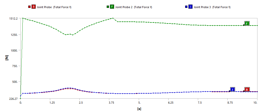
Figure 4: The Force Reaction From Translational Joints
Based on the simulation results, engineers can then make design modifications or optimizations to improve the arm's performance. This iterative process of simulation and design refinement helps engineers create a robot arm model that meets the desired performance criteria.
Overall, designing and building a robot arm model in ANSYS Motion requires a combination of mechanical engineering knowledge, simulation expertise, and an understanding of the arm's intended application and performance requirements.