
A hologram is a three-dimensional image formed by the interference of light beams that have been scattered off an object. Unlike a photograph, which records only the intensity of light, a hologram records both the intensity and the phase of light. This allows a holographic image to appear three-dimensional, exhibiting parallax and depth as the viewer's perspective changes.
The process of creating a hologram involves using a laser to split light into two beams: an object beam and a reference beam. The object beam illuminates the object, and its light is scattered onto a recording medium (such as a holographic plate or photosensitive material). The reference beam is directed straight onto the recording medium. The interference pattern between the object and reference beams is recorded on the medium, creating a hologram.
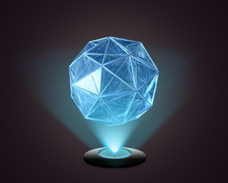
Figure 1 Typical image of hologram
When illuminated with coherent light, such as a laser, during playback, the hologram reconstructs the original light waves, producing a three-dimensional image that appears to float in space. Holography finds applications in art, security features on credit cards, holographic displays, and other fields where three-dimensional visualization is valuable.
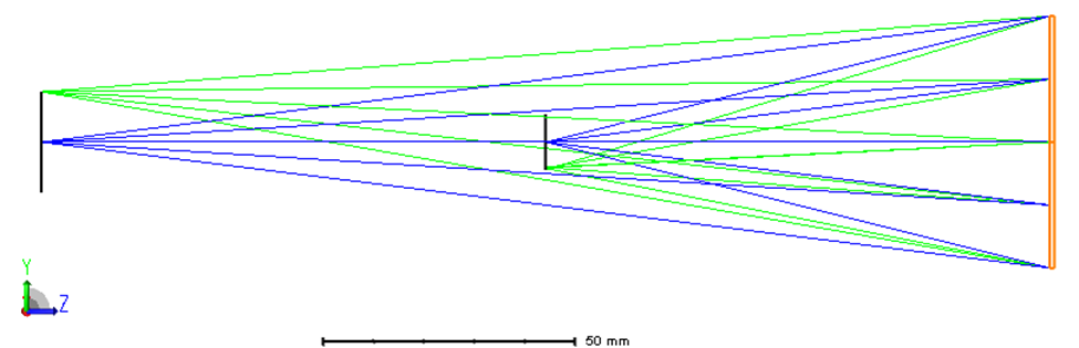
Figure 2 Layout of hologram in reflection
Hologram surface (orange in Figure 2) can be used to model optically constructed holograms. The hologram surface can be plane, spherical, or conical, and the medium behind the hologram can be air or glass. The glass can also be "MIRROR" which indicates the hologram is constructed and used in reflection. The hologram itself is described by the x, y, and z coordinates of a surface sag map is shown in construction points (Figure 3), a construction wavelength, and the diffraction order.
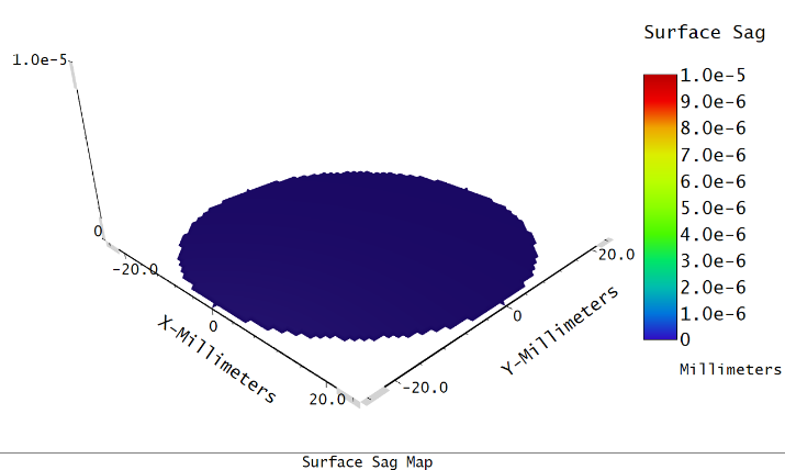
Figure 3 Surface sag map in mm
Holograms are constructed and used in transmission or reflection. There are occasions where the hologram is constructed in transmission, and then the substrate is aluminized and used in reflection. This special case can be simulated with the hologram surface by specifying a negative construction wavelength.
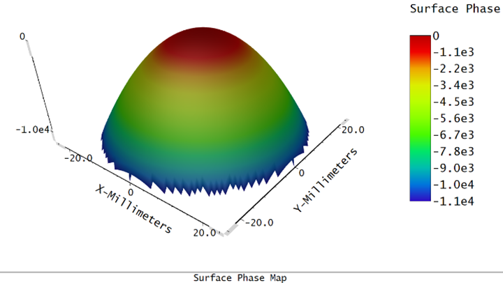
Figure 4 Surface phase map in periods of 2π
Surface phase in Figure 4 accounts for the size and shape of any aperture present on the surface, even if the aperture is decentered. The phase is computed on a uniform grid of points in XY plane, and the phase value is the displayed data. This feature defines phase in units of periods. One period represents a phase change of 2π. Surfaces which do not impart a phase change to the ray, such as the standard surface, will display a phase of zero everywhere on the surface phase display.
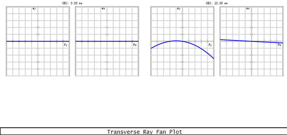
Figure 5 Optical aberration in both fields (maximum scale: 1 mm)
This system comes with two fields, 0 mm and 10 mm in object height. Figure 5 shows ray fan of both fields at image plane. It typically shows how rays from different field points and object heights converge or diverge through the optical system. The hologram surface generally does not induce significant aberrations. As seen, the aberration is limited in 0.5 mm.
For holography, it's crucial to use software that understands the principles of interference and diffraction, which are central to holographic image formation. Zemax is a powerful tool in optical design and analysis for all kinds of optical systems including hologram construction.
