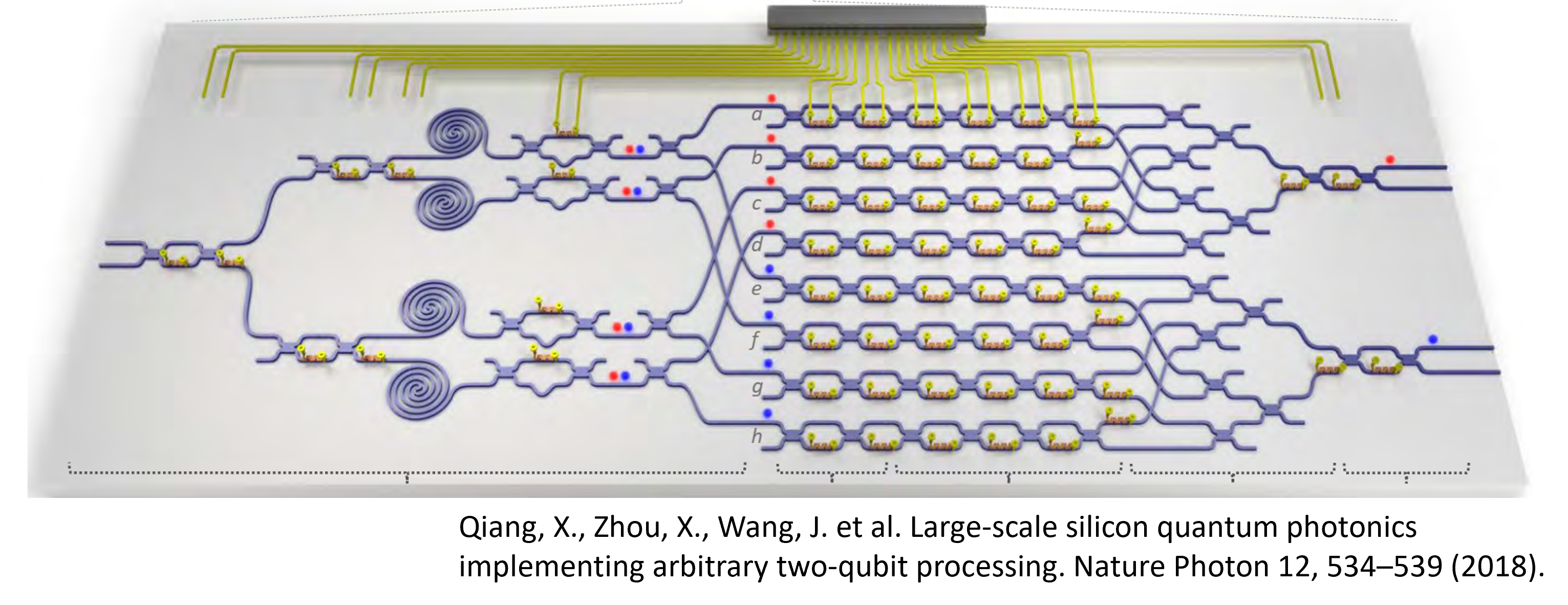
Integrated Quantum photonics (IQP)
- IQP is emerging as a viable alternative to quantum computation
- Research in areas such as quantum sources, waveguides and modulators has made this possible
- Compatibility with CMOS technology means industrial scalability will be much easier
Basic components of quantum photonics
The basic components of a IQP system are:
- Sources (e.g QDs in Cavities)
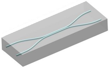
- Waveguides
- Directional couplers (beam splitters)
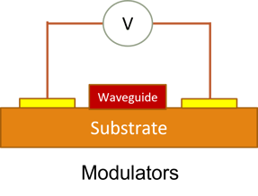
- Modulators
Lumerical for quantum photonics
Here we show how various Lumerical modules can be used to design IQP components. We focus on:
- Photonic crystal (PC) design:
- QDs embedded in PCs are popular sources of single photons
- Q factor calculations
- Waveguide design including loss analysis
- Calculating bending loss
- Modulator analysis
- Calculating charge distribution using CHARGE
- Using MODE to calculate change in refractive index for different charge distributions
- Analysis of Frequency conversion in waveguides
- Analysing frequency conversion in waveguides
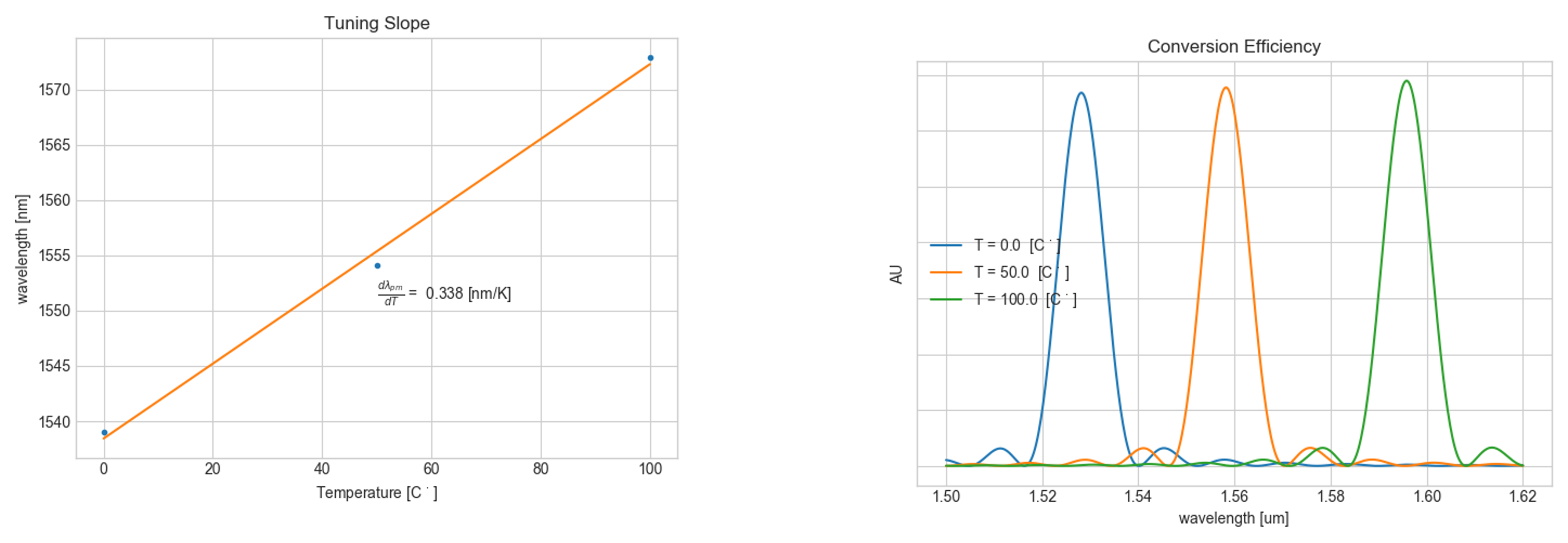
- Analysing dispersion with temperature
- Calculating conversion efficiencies at different temperatures
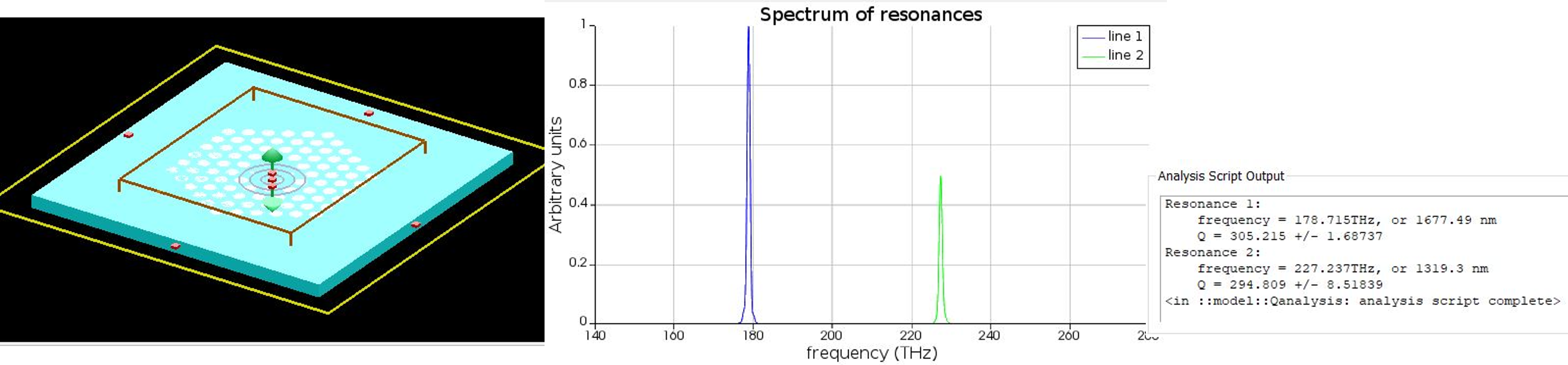
Photonic crystal (PC) design using Lumerical
- Quantum dots embedded in PC cavities are some of the most popular sources of single photons
- Lumerical FDTD can be used to Q factors of such cavities
- Q-factor can be calculated by analysing the time signal, especially for high Q cavities
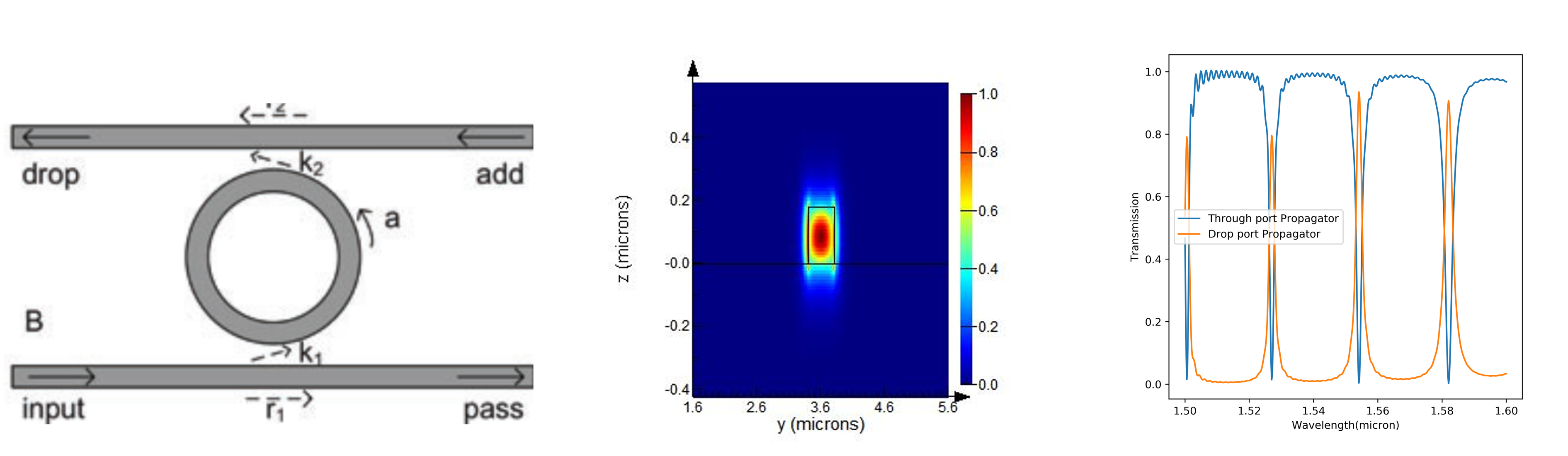
Ring resonator cavity design using Lumerical
- Another popular architecture is the ring-resonator architecture for cavities
- Lumerical FDTD can be used to Q factors of such cavities using time signal decay
- A waveguide mode can be launched in the input port and transmission can be measured in the drop port and the through port. By changing the radius of the ring, the resonances can be shifted in frequency
Waveguide design and loss analysis
MODE can be used to:
- Calculate various modes of a waveguide with information like n_eff and loss
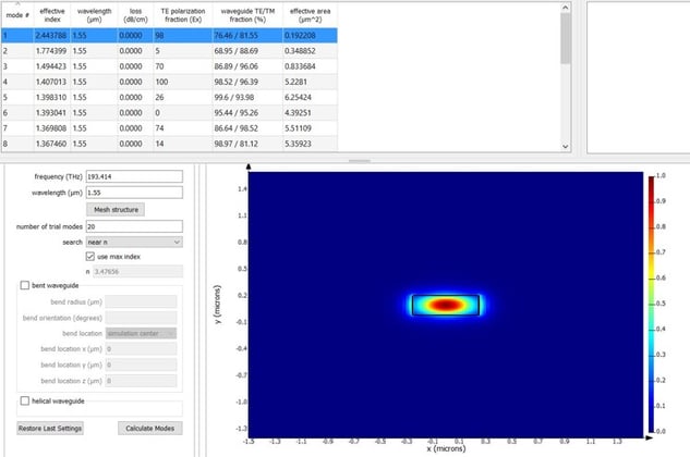
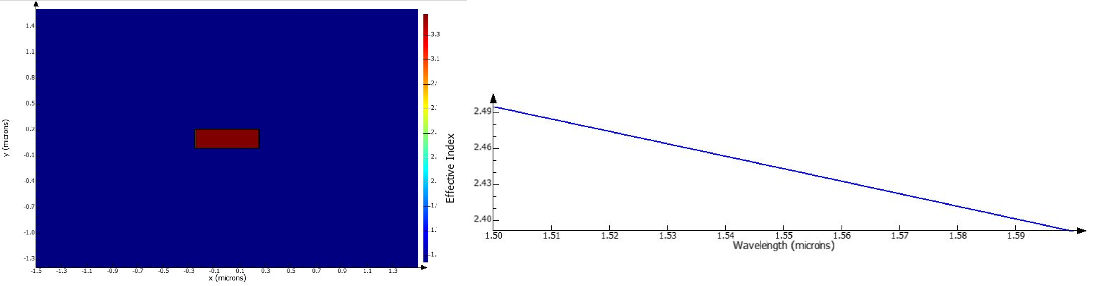
- Perform frequency sweep to calculate effective index for a particular mode at different wavelengths
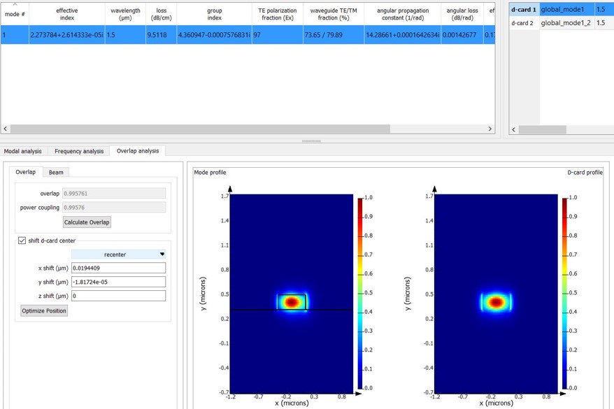
- Calculate the bending loss by calculating the mode effective index and loss/cm for a bend with a certain radius. Here we see the loss for bend radius of 1.5 um.
- Calculate overlap of modes between a bend and a straight section of the waveguide. This has to be factored in during bending loss calculations. Here we see overlap integral of 0.9957 for a straight WG mode and one with a bend radius of 10um.
Modulator
- Here we demonstrate how a PN modulator can be modelled using Lumerical CHARGE
- CHARGE can be used to calculate the charge densities for different values of applied electric fields
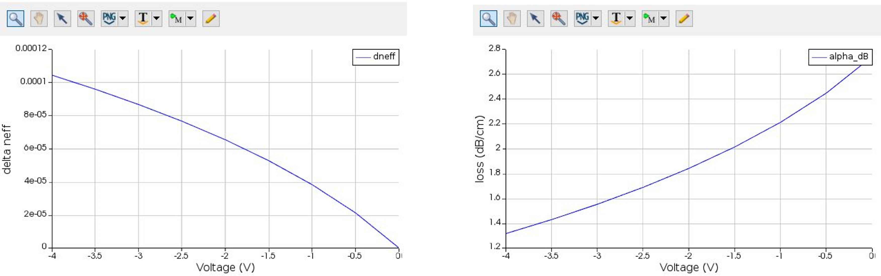
- Changing charge densities change the refractive index of the waveguide and hence causes a phase change in the propagating mode
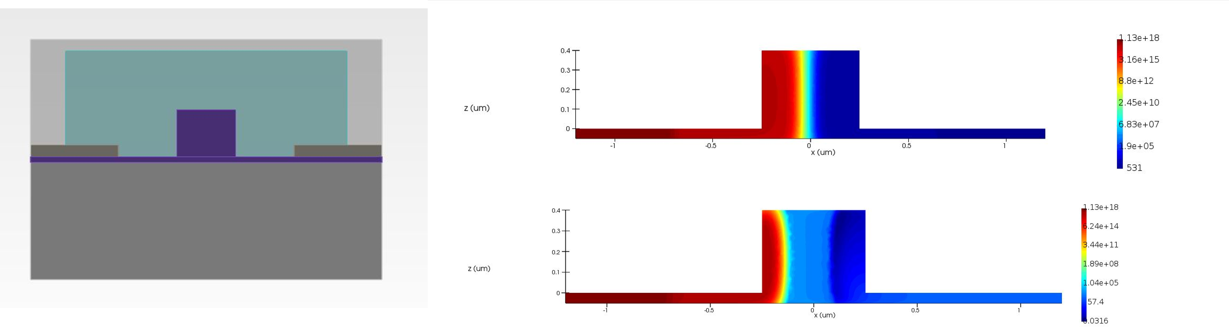
- Here we demonstrate how a PN modulator can be modelled using Lumerical CHARGE
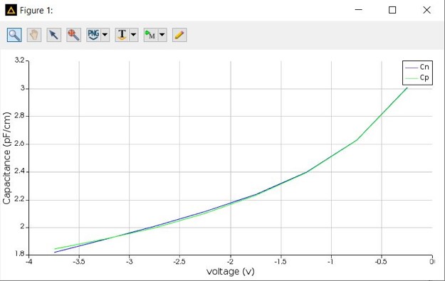
- CHARGE can be used to calculate the capacitance for different voltages
- This capacitance gives information on how fast can a modulator be used
- CHARGE can export the obtained charge distribution and this can be used by MODE solutions to calculate fundamental mode properties at different voltages
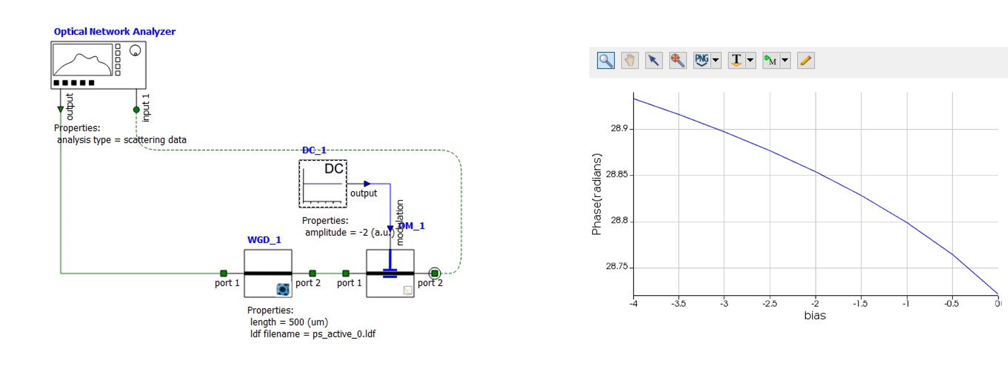
Measuring phase change during modulation
INTERCONNECT can be used to measure phase change using the designed modulator. MODE solutions can be used to export effective refractive index for different voltages. This can be imported in INTERCONNECT to calculate modulation for different voltages.
Lumerical for frequency conversion
Number of IQP protocols use frequency conversion for generating photons. For e.g. in Lithium Niobate Lumerical (MODE) can be used to calculate how modes for fundamental and SHG (second harmonic) change with temperature.
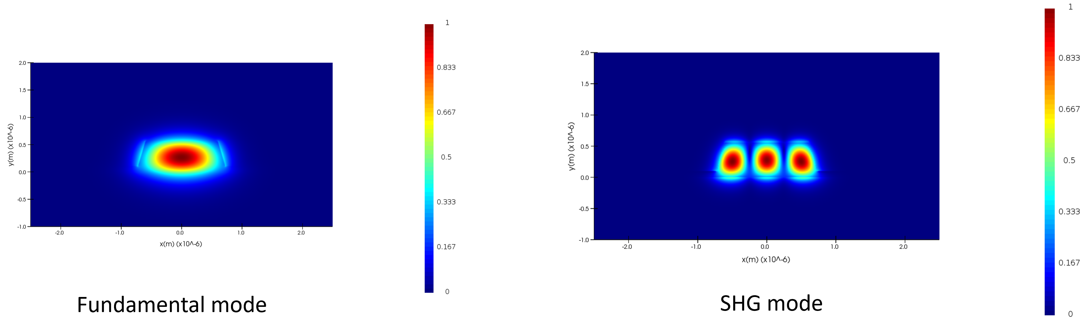
Using Sellmeier coefficients to model the refractive index of Lithium niobate at different temperatures we can obtain mode dispersion for fundamental (tel) and SHG (nir) at different temperatures
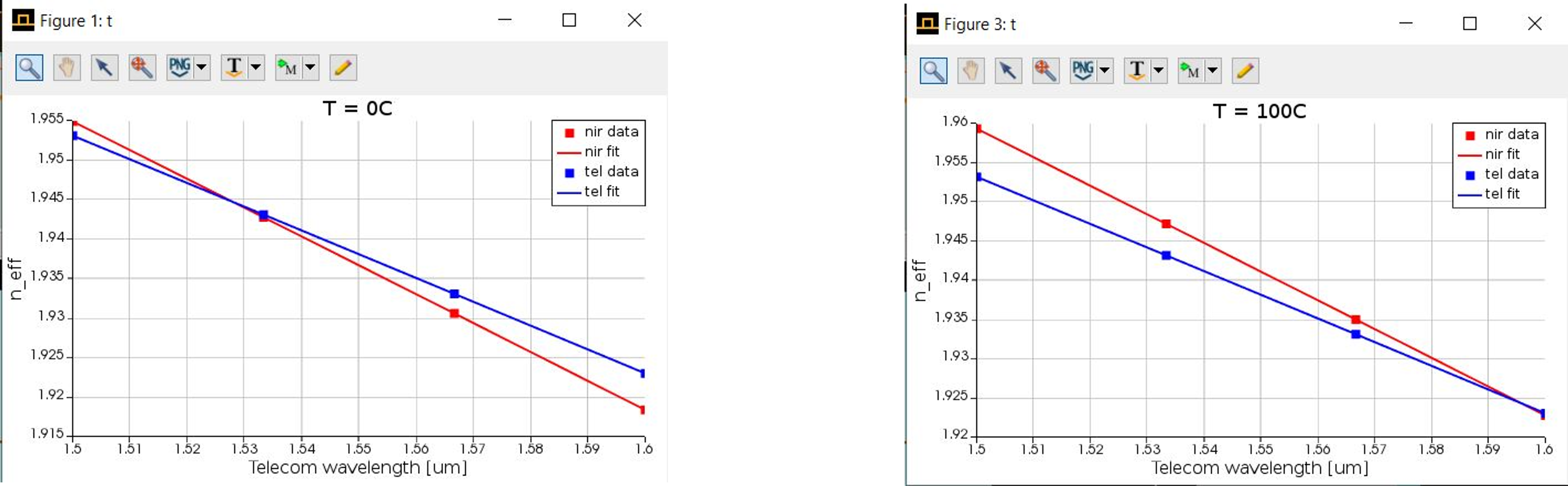
Using the dispersion data we can find phase matching fundamental wavelengths at different temperatures. We see that the fundamental wavelength shifts to higher values with increasing temperature.