
Backdrilling is a technique used in high-speed digital circuits to remove excess via stubs that can cause signal reflections and degrade circuit performance. Defining it in HFSS 3D Layout previously required assigning a specific layer, and often dummy layers were created to control its depth or length. However, in the latest Ansys release, "23R1," a more flexible approach is provided. Here, I will be showing you how to set an arbitrary backdrill depth in HFSS 3D Layout. So, let's get started!
Overview
Let's take a look at this simple example where we have a differential via.
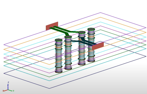
Differential via example in HFSS 3D Layout
If we examine the backdrill section in the "Padstack Usage and Definition" window of the previous release of HFSS 3D Layout, "22R2", we can see that the backdrill can only be configured by a specific layer:
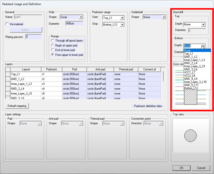
Padstack Usage and Definition window in HFSS 3D Layout "22R2"
Now, let's take a look at the backdrill section in the latest Ansys release, "23R1":
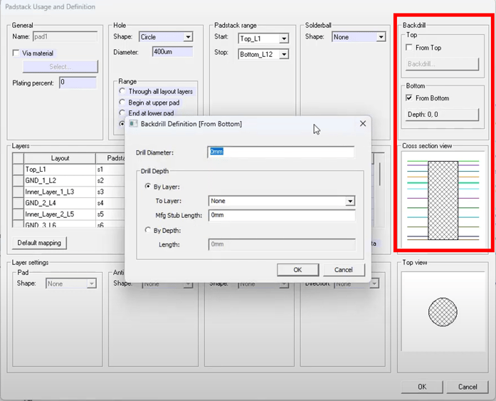
Padstack Usage and Definition window in HFSS 3D Layout "23R1"
With this new method, the backdrill can be set by depth, by layer with an offset, or by a specific layer. We can not only set the depth of the backdrill, but also the radius, which can be larger or smaller than the via itself.
The following video provides a quick demonstration of how to set arbitrary backdrill in HFSS 3D Layout: