LIDAR BASICS
- LIDAR is based on well known principles of RADAR
- Radar is well known technology existing since the beginning of the 20th century
- LIDAR uses optical frequencies instead of radio waves
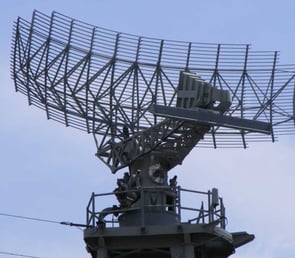
Lidar and Radar
LIDAR using phased arrays improves directionality using interference
- Output profile of a LIDAR is the product of the array factor and the single antenna far field.
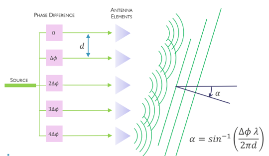
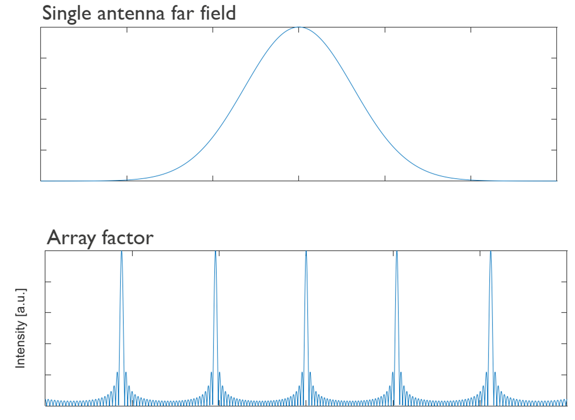

N: number of antennas
k: wave vector
w_i: complex weight for element I
r_i: position vector for antenna element i

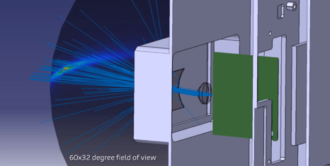
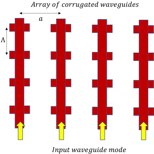
LIDAR using on-chip waveguide antennas
- Corrugated waveguides are used as antennas
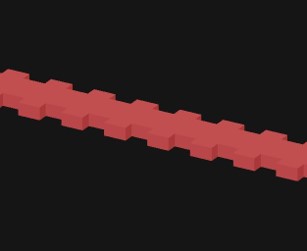
- Pitch corrugation is chosen so that Bragg reflected light is scattered to free space

- Multiple such antennas are used in an array to for beam forming
Lidar modeling in Lumerical
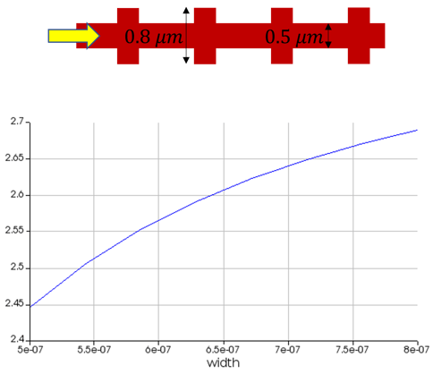
- MODE analysis of waveguide to calculate n_eff
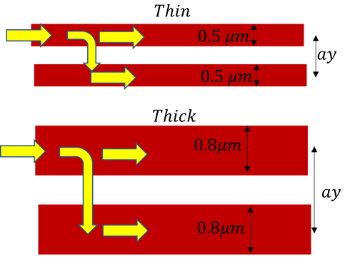
- Choosing optimum antenna separation so that there is minimum coupling between adjacent antennas
- 3d FDTD simulation to calculate bandgap region
- Far field analysis to calculate far-field profile of a single antenna
- Array factor multiplication to see beam steering
Mode
Calculate effective refractive index for thinner and thicker cross-sections
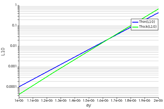
- Optimizing separation to minimize cross-coupling
- We perform simulations with 2 waveguides and calculate after how much length can 10% of light from waveguide 1 couple to waveguide 2
FDTD
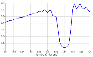
- Calculate the band-gap region
- Observe wavelength dependent single antenna scattering
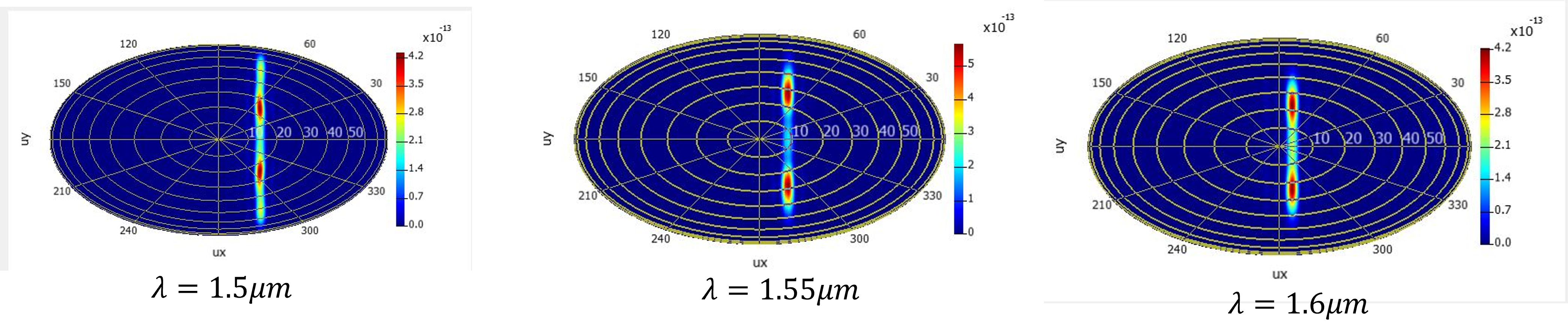
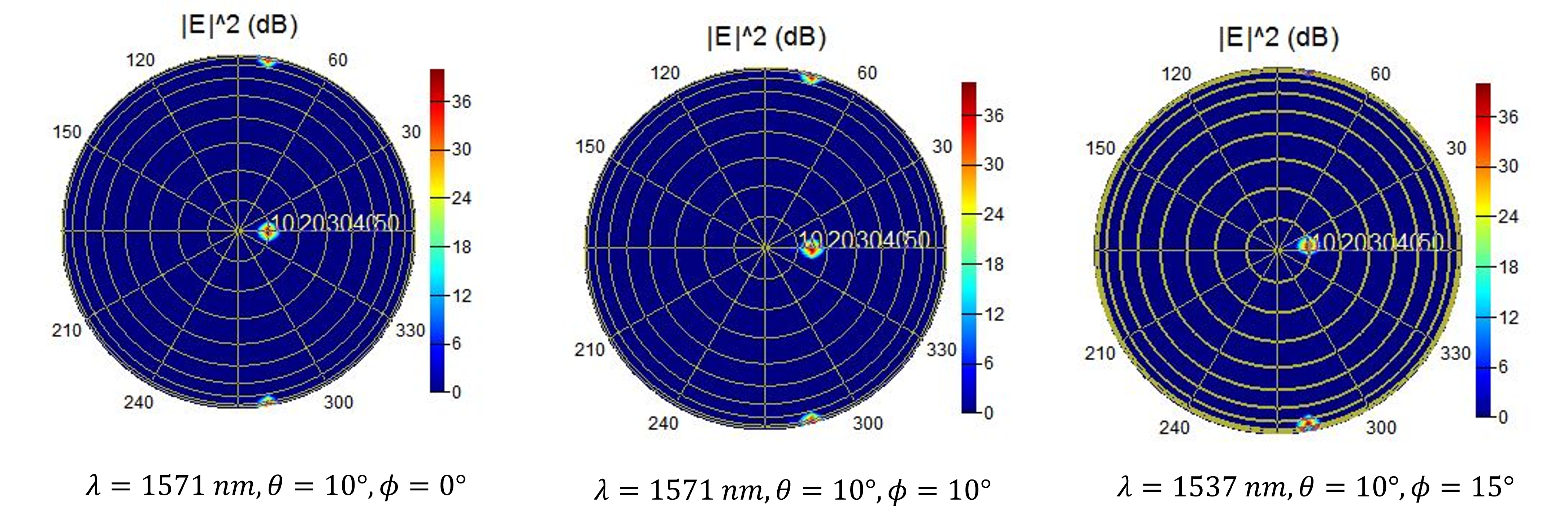
- 2d beam-steering(θ,ϕ) using results from FDTD
System level simulations using INTERCONNECT
- Integrate multiple components
- Simulate an actual experiment
- Extensive library of standard components
- Custom components can be created
- Allows integration of optical, electrical and thermal elements
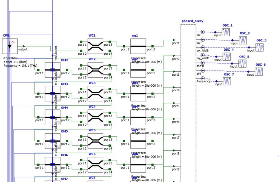
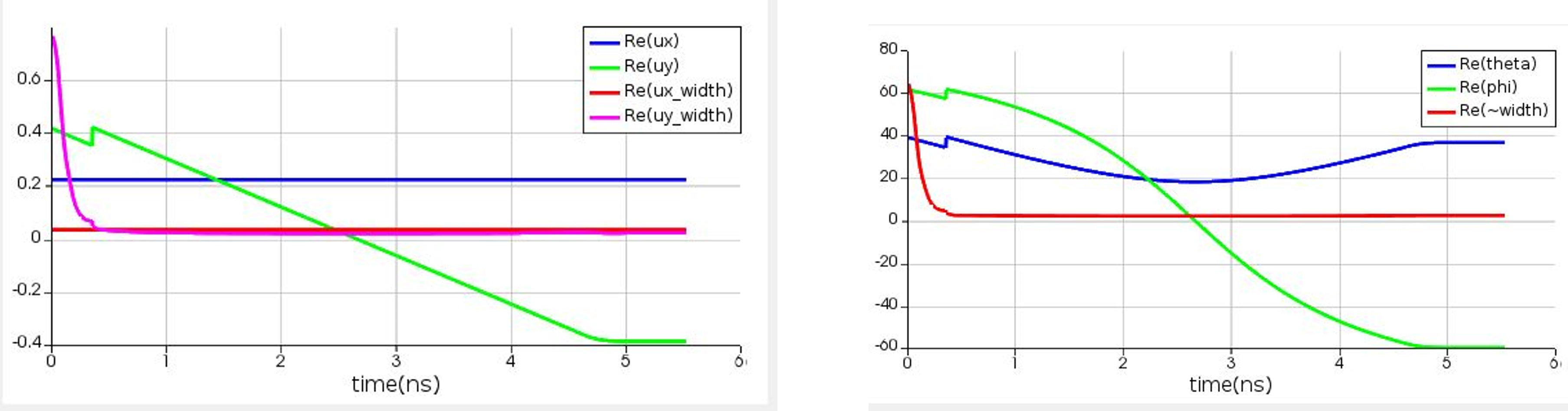
- We see the effect of applying a optical delay using a voltage ramp on an optical modulator
- For a given range of voltage values we can monitor θ,ϕ of the steered beam and beam properties.
Beam Steering
Detector design
- Detector design using Lumerical
- Optical simulations to study light absorption in detectors
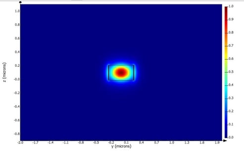
Example: We look at Germanium detectors on Si
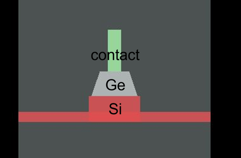
Ge on Si detector cross-section
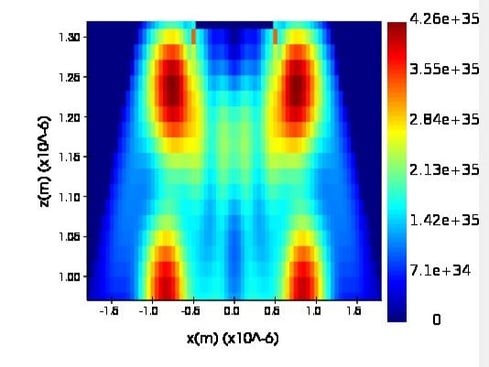
Intensity profile in Ge using FDTD
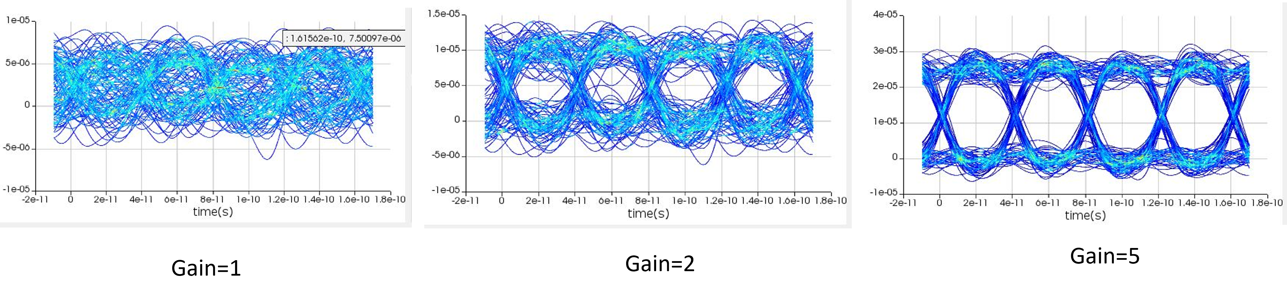
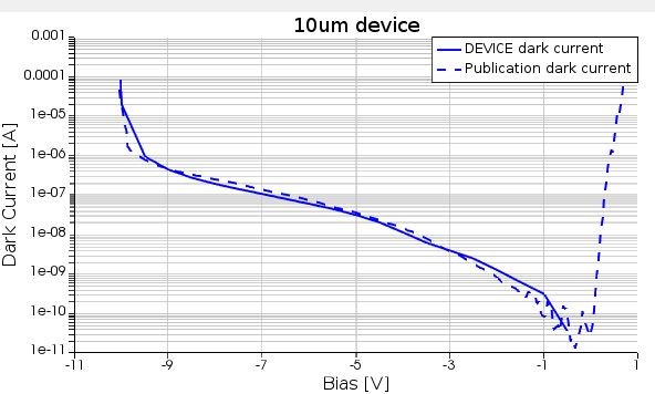
- Electrical simulations using CHARGE can be used to calculate the photocurrent and the dark current for the detector
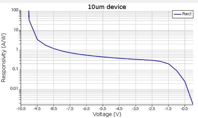
- Electrical simulations using CHARGE can be used to calculate the responsivity and gain
- Circuit simulations using INTERCONNECT can be used to simulate detector response to weak modulated signal