SUMMARY
In the world of composite material analysis, precision is everything, especially when defining fiber orientations and ply layups. Ansys ACP (Ansys Composite PrepPost) offers powerful tools to establish reference directions, a critical step in achieving accurate structural simulations. In this blog, we’ll demystify the methods for creating reference directions in Ansys ACP, highlighting their simplicity and versatility. By mastering these techniques, you can unlock the ability to define intricate composite patterns with minimal input, streamlining your workflow and enhancing the fidelity of your simulations. Whether you're tackling a straightforward design or a multi-ply, curved geometry, understanding reference directions is the key to success. Let’s dive in!
Steps before creating the reference directions:
This is a short remainder of the previous steps, they will be used to present the example model too.
- Create a shell geometry and mesh. In this step, don't forget to add a thickness value and a material to the geometry inside the meshing environment. These definitions don't affect the final composite structure.


- Define material in Engineering data. As usual in your composite model, include orthotropic properties and failure criteria as needed.

- Define a Fabric in ACP. Defining material and thickness.

- Define rosettes. In the Ansys environment, these are referred to as coordinate systems. They are the most important input for creating reference directions, along with the initial mesh. To create rosettes, two axis and one origin point are necessary.

Reference directions:
The reference direction is the in-plane vector that defines the zero-degree orientation for each element. Based on this direction, multiple layers can be defined with varying orientations relative to the reference. It is also possible to define multiple reference directions within the same element by using Oriented Selection Sets (OSS). For complex geometries, defining each element individually can be a challenging task.
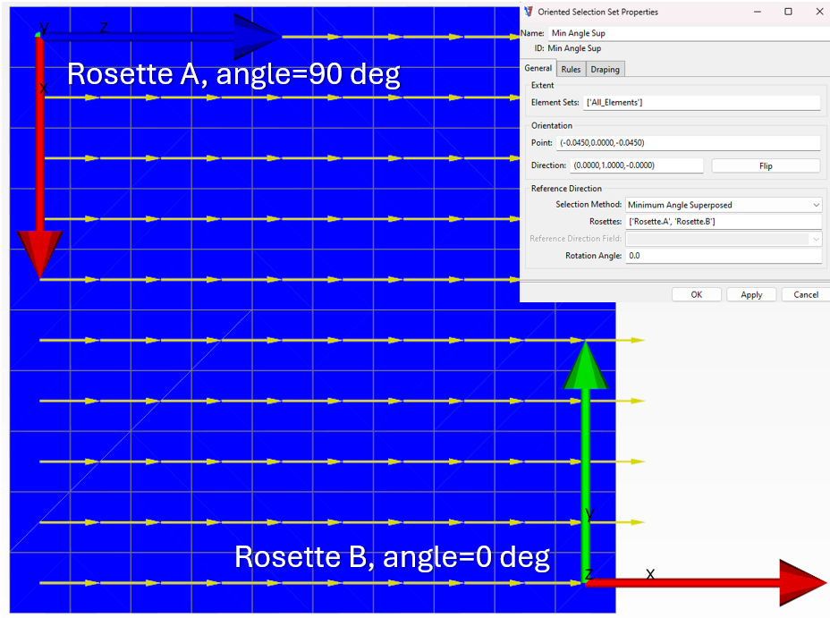
When defining the Oriented Selection Sets, the 'Reference Direction' section can be found at the bottom of the 'General' tab. The 'Extent' and 'Orientation' sections allow you to specify the element set to which the definition applies and the normal direction (lay-up growth).

Note in the 'Reference Direction' section the 'Rosettes' and 'Selection Method' fields. They are the main focus of this blog entry.
Rosettes:
First, consider these two Rosettes (A and B). Both are parallel to the global coordinate system, but none of their directions are oriented with the global system.

Selection method:
The selected method considers the relation between the Rosette Z-axis and element Z-axis (defined during the shell element creation) to define the reference direction. This can be copied from a Rosette X-axis or calculated by interpolation (X-axis) depending on the selected method.
- Minimum Angle: Selects the Rosette whose Z-axis forms the smallest angle with the element normal vector. In this example, the angle between the element and Rosette B is zero, while the angle for Rosette A is 90 degrees. That is why the reference direction (yellow vectors) is parallel to the Rosette B X-axis (copied). There is also a Maximum angle algorithm option working with the maximum angle.

- Minimum Distance: Selects the Rosette closest to each element and assigns its X-axis direction as the reference direction for that element. Note in this definition the global coordinate system has been included. The Maximum Distance option is not available.

- Minimum Distance Superposed: Interpolates the X-axis direction for all selected Rosettes based on distance. Note the similarity with Minimum Distance.


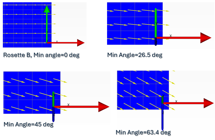
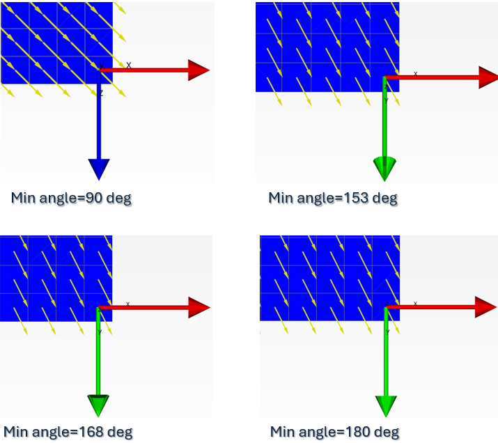
Now, successive rotations around local X-axis are applied to the Rosette B making the difference angle to increase from 0 to 180 deg, modifying the weight factors and therefore, the reference direction.


CONCLUSION
By mastering the process of defining reference directions in Ansys ACP, you lay the groundwork for more precise and reliable composite material simulations. This understanding not only improves your designs but also saves valuable time in your workflow. Whether you're a seasoned analyst or a newcomer to composite modeling, these techniques empower you to tackle complex challenges with confidence. With a firm grasp on reference directions, the possibilities for innovation in composite design are limitless.Ozen Engineering Expertise
 Ozen leverages its extensive consulting expertise in CFD, FEA, optics, photonics, and electromagnetic simulations to achieve exceptional results across various engineering projects, addressing complex challenges like multiphase flows, erosion modeling, and channel flows using Ansys software.
We offer support, mentoring, and consulting services to enhance the performance and reliability of your hydraulic systems. Trust our proven track record to accelerate projects, optimize performance, and deliver high-quality, cost-effective results for both new and existing water control systems. For more information, please visit https://ozeninc.com.
Tags:
FEA, Structural Analysis, ANSYS Mechanical, Setup Productivity, Composite Materials, ACP- Ansys Composite Preprocessor, Reference directionDec 20, 2024 7:52:38 AM
