
Interference is a phenomenon that occurs when two or more waves overlap. In the case of an optical interferometer, light waves are used. When two or more light waves combine, they interfere with each other, resulting in a pattern of alternating bright and dark regions called interference fringes. In an interferometer, a beam of light is split into two or more separate beams that follow different paths. These beams then recombine, and interference occurs when they meet again. The difference in path length traveled by the beams can be manipulated to produce interference fringes that are sensitive to changes in certain properties.
There are various types of optical interferometers, including Michelson interferometers, Fabry-Perot interferometers, and Mach-Zehnder interferometers. In Michelson Interferometer, a beam of light is split into two perpendicular paths and then recombined. It is commonly used for measuring the wavelength of light, determining refractive indices, and detecting small displacements. Fabry-Perot Interferometer uses multiple reflections between two partially reflective mirrors. It is often used to measure the wavelength of light and for spectral analysis. Mach-Zehnder Interferometer has two beam splitters and two mirrors arranged in a way that creates interference fringes. It is commonly used for applications such as measuring small displacements, phase changes, and testing optical components.
Here we demonstrate a Mach-Zehnder Interferometer model in Ansys Zemax. Figure 1 shows typical layout of the Mach-Zehnder Interferometer. Figure 2 presents the optical setup of Mach-Zehnder Interferometer.
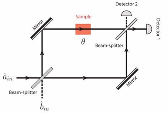
Figure 1 Optical Layout of Mach-Zehnder Interferometer
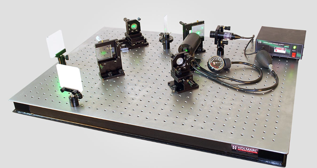
Figure 2 Typical optical setup of Mach-Zehnder Interferometer
Figure 3 shows the Zemax model of Mach-Zehnder Interferometer in non-sequential mode. Figure 4 shows the corresponding component editor. Note the 50% coating on the front faces of the beam splitter plates. A He-Ne laser beam is split at the first splitter and recombined by the second splitter. One of the mirrors is at a slight angle with respect to the second, and so the beams are recombined with some tilt.
The coherent sum of the ray amplitudes shows the interference fringes between the two beams. ZEMAX can model any form of shearing interferometer using this technique. The total power is conserved between incoherent and coherent additions, but that the peak irradiance of the coherent beam is 2x that of the incoherent beam sum, as it should be.
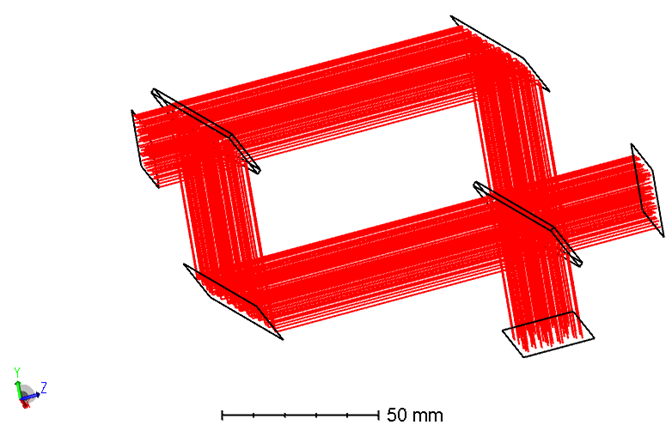
Figure 3 Zemax model of the Mach-Zehnder Interferometer
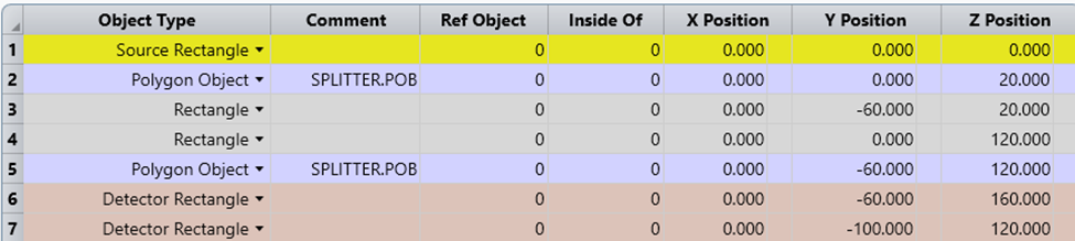
Figure 4 Non-sequential object list of the Mach-Zehnder Interferometer
The beams emanating from the rectangular source positioned at the upper left corner of the arrangement undergo division through a 50/50 coating on the front surface of the Polygon Object associated with object 2. Subsequently, these beams traverse down the two arms of the interferometer towards the detectors (objects 6 and 7) located at the lower right side. The recombination of the two ray paths before reaching the detectors is facilitated by a second Polygon Object (object 5) featuring a 50/50 coating. Notably, the mirror situated in the lower left arm of the interferometer (object 3) experiences an additional tilt of 0.005 degrees about the x-axis. This tilt results in unequal path lengths in the beam at the surfaces of the detectors.
Leveraging its coherent detection capabilities, Zemax combines the energy from the rays reaching the detectors coherently, considering the amplitude and phase of each detected ray. This feature enables Zemax to effectively simulate phenomena like fringes in interferometers. To observe these effects, it is essential to configure the Show Data setting in the Detector Viewer settings to either Coherent Irradiance or Coherent Phase. Figure 5 shows the coherent irradiance of detector object 7, which clearly presents interference fringe. Figure 6 shows coherent irradiance at cross section row of detector object 6.
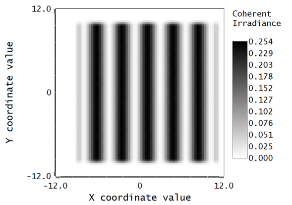
Figure 5 Interference fringe at coherent detector (object 7)
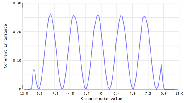
Figure 6 Coherent irradiance at cross section row (object 6)
Access the settings of the Detector Viewer, adjust the Show Data option to Incoherent Irradiance for both detectors 6 and 7. Notice that the absence of fringes is evident, as the detector is no longer observed from a coherent perspective.
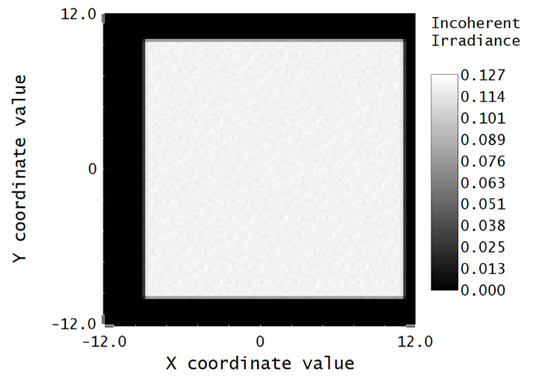
Figure 7 Incoherent irradiance at detector (object 7)
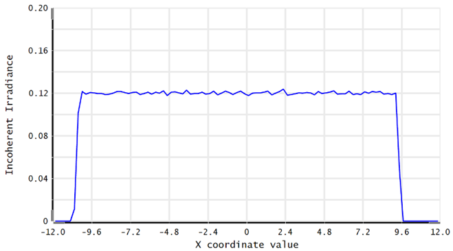
Figure 8 Incoherent irradiance at cross section row (object 6)
From quantitatively assessment of these interference fringes, optical interferometers have a wide range of applications, including in astronomy for measuring the size of celestial objects, in metrology for precise distance measurements, in microscopy for improving resolution, and in various fields of physics and engineering for detecting small changes in conditions. Overall, optical interferometers are powerful tools for making accurate and precise measurements in a variety of scientific and technological domains. Zemax facilitates the design of interferometers by providing a powerful set of tools for modeling, simulation, analysis, and optimization of optical systems.
