
Optical testing fixture is a device or setup designed to evaluate and assess the performance of optical components, devices, or systems. These fixtures are commonly used in various industries. The primary goal of optical testing is to ensure the accuracy, quality, and reliability of optical devices and systems.
Below is a typical optical lens testing station model in Zemax non-sequential mode. The purpose is to evaluate the characteristics of lenses, such as focal length, focal point diameter, distortion, and aberrations. The fixture holds the lens in a precise position relative to the testing equipment. For instance, focal length testing, this fixture is a specialized setup designed to accurately measure the focal length of optical component (marked in orange in Figure 1). The focal length is a critical parameter that defines the distance from the lens to the image or focal point, the last plane of the system.
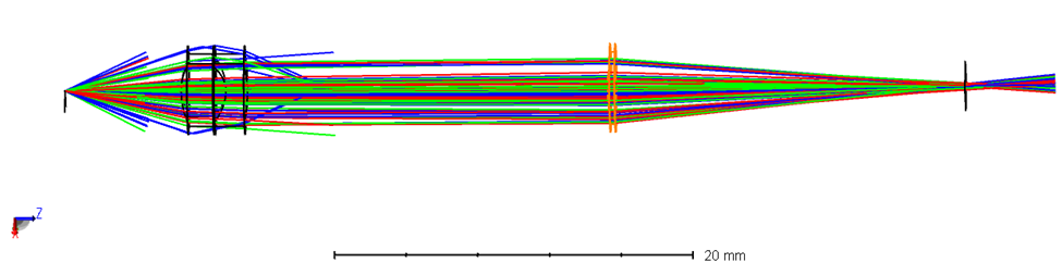
Figure 1 Test fixture configuration
The main optical components of the above system are off-the-shelf parts from Thorlabs. The light source is a white light LED from Thorlabs, part No: LEDW7E. This source emits white light in the wavelength range in 430-660 nm, as shown in Figure 2. The half viewing angle is about 7.5°, indicated in Figure 3.
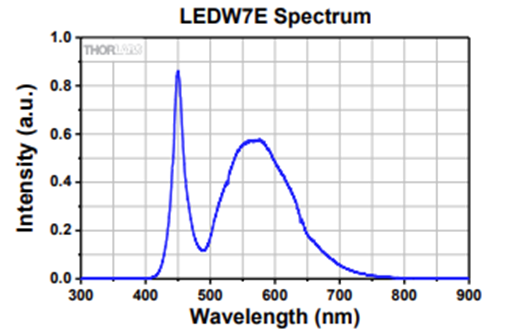
Figure 2 Emission band of the LED source
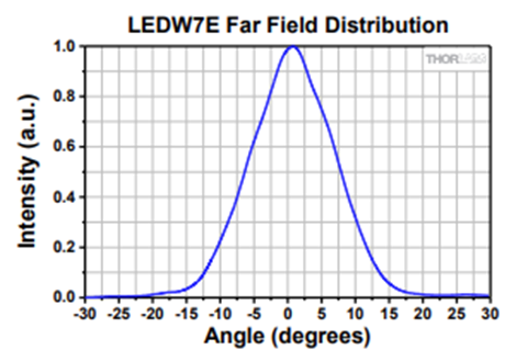
Figure 3 Emission angle of the LED source
To model this LED source in Zemax NSQ mode, the “source diode” is selected as source type, where allowing X and Y-divergence assignment. In this case we input 7.5 in both X-divergence and Y-divergence blank, as the object 3 in Figure 4. The wavelength can use the default setting in Zemax in visible light, with primary in 588 nm as in Figure 5.
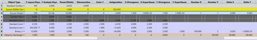
Figure 4 Emission angle of the LED source
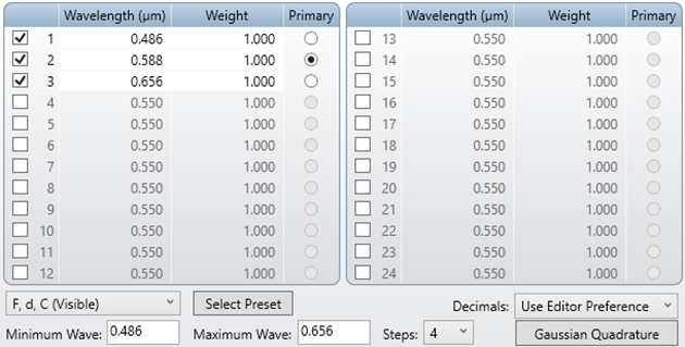
Figure 5 Wavelength setting
The collimating lens was selected as Thorlabs AC050-010-A-ML. The piece structure is shown in the figure below. This doublet is designed with 5 mm aperture and 10 mm back focal length. It allows a good amount light collection of the 7.5° emission angle, as 2*tan(7.5)*10 = 2.6 mm, which is less then the full aperture size of 5 mm. Choosing the doublet structure is for balancing the chromatic and spherical aberration.
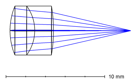
Figure 6 Collimating lens structure for the LED source
The lens to be tested, i.e. the orange part in Figure 1, is placed in the collimated light path. The clearance is about 4 mm in diameter. This size allows collimated light to pass through the full aperture. It is located 6 mm away from the collimator, allowing some flexibility of mechanical components. The focal length can be reflected with assistance of a camera sensor, which is the last component in Figure 1. It locates at the focal point of the lens being tested, i.e. object 9 in Figure 4.
The light is focused on the camera sensor as below. The smallest center point suggests the best focus status of the lens to be tested. Although it can not be a point, due to aberration, diffraction, the smallest point size is the point that at the best performance of focus.
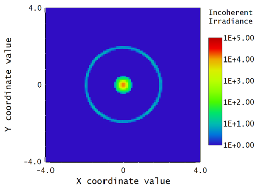
Figure 7 Focused energy distribution at camera sensor
This collimation and focusing structure can be widely used in general optical testing fixture construction. The testing procedure typically involves adjusting the lens position until a focused image is obtained on the target or image sensor. The distance between the lens and the focused image, along with other parameters, is then used to calculate the focal length. It's important for the fixture to provide a stable and controlled environment to ensure accurate measurements. Professional calibration of the fixture and its components is crucial for obtaining reliable results. Additionally, the fixture should be designed to accommodate various types and sizes of lenses, and it should be user-friendly for ease of operation.
