
Optical prism is a transparent optical element with flat, polished surfaces that refract light. The most common type of prism is a triangular prism, which has two triangular bases and three rectangular or slightly trapezoidal faces. Prisms are often made of materials like glass or acrylic. When light enters a prism at an angle, it undergoes refraction, or the bending of light, as it passes through the prism. This bending of light is due to the change in the speed of light as it passes from one medium (air) into another (the material of the prism). The degree of refraction depends on the angle at which the light enters the prism and the refractive index of the prism material.
Abbe roof prism, also known as the Amici roof prism, is a type of prism used in optics for image inversion and erecting. A typical use is telescopes, as shown in Figure 1. The Abbe roof prism is a modification of the classic roof prism, which is commonly used for compact and straight-line optical paths in binoculars and other optical devices.
The Abbe roof prism consists of two right-angled prisms cemented together at their hypotenuse faces. This arrangement results in a roof-like structure with a 90-degree bend in the optical path, similar to the standard roof prism. However, the key innovation of the Abbe roof prism is the addition of a total internal reflection (TIR) surface on one of the prisms, which enables the inversion of the image without inverting the object.
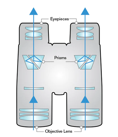
Figure 1 Abbe roof prism in telescope
A model of Abbe roof prism is shown in Figure 2, which is setup in mixed sequential and nonsequential system. The prism is configured with ABBE_ROOF.POB. The .POB file is a preset template for polygon objects. When the corresponding type of .POB file is selected, the only required inputs are geometrical dimensions, as shown in Figure 3.
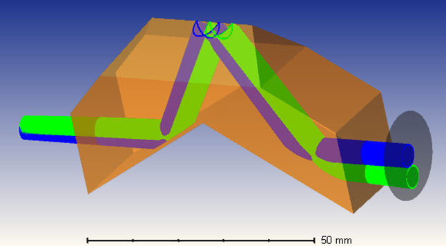
Figure 2 3D layout of Abbe roof prism
![]()
Figure 3 Nonsequential component editor (POB dimensions)
With the dimension-defined prism object, the non-sequential object is placed in the sequential layout with properly defined exit locations, to form a mixed mode. A Mixed-Mode system is a sequential system that contains non-sequential objects. To perform a ray trace through such a system, Entry and Exit Ports must be used to define the beginning and the end of the NSQ group, as demonstrated in Figure 4.
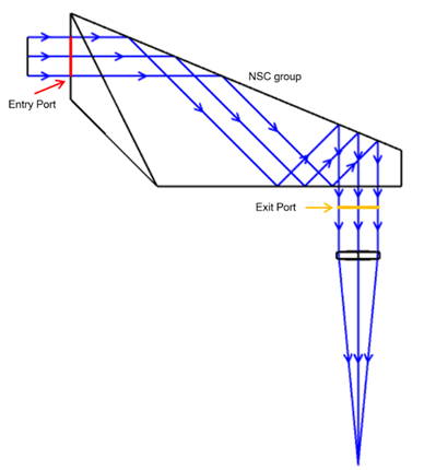
Figure 4 Key components of prism in Zemax mixed mode
Figure 5 is the lens data list of the mixed-mode system. Entrance pupil diameter is selected as pupil, with the value of 5 mm in uniform apodization. The fields in this system are set to 0 and 3 degrees in degrees, as shown in Figure 6.
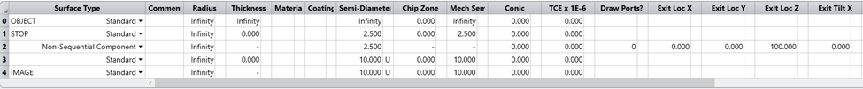
Figure 5 Lens data editor of the mixed model
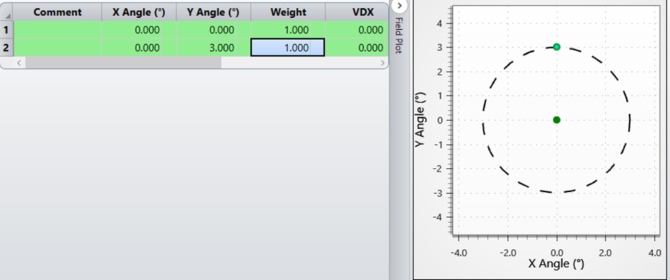
Figure 6 Field setting of the mixed model
Figure 7 explicitly demonstrates how beam propagates inside the Abbe roof prism. The incident beam of light enters the Abbe roof prism through one of its faces. Consider the entry through the longer leg of the prism. As the light enters the first prism, it undergoes refraction at the first air-to-glass interface. The prism is typically made of glass, and the refraction bends the light toward the normal. The key feature of the Abbe roof prism is the introduction of a total internal reflection (TIR) surface on one of the prisms. This TIR surface is applied to the hypotenuse of the first prism. As the refracted beam encounters this TIR surface at an angle greater than the critical angle, it undergoes total internal reflection. The internally reflected beam reflects off the TIR surface and transposes to the other prism. The reflection inverts the direction of the beam.
The beam then enters the second prism, and it undergoes refraction at the second air-to-glass interface. This refraction bends the light away from the normal. The light exits the Abbe roof prism through one of its faces. In the case of telescopes and binoculars, this light may continue through additional optical elements before reaching the eyepiece or viewer. The combination of reflections and refractions in the Abbe roof prism results in an optical path inversion. This means that the image formed by the telescope or binoculars is correctly oriented, making it suitable for terrestrial observations.
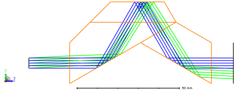
Figure 7 Optical propagation inside the Abbe roof prism
Regarding polarization modulation by Abbe roof prism, when a Jones vector of vertical polarization is applied to the incident light, such as [0,1]. The polarization status in the image plane is listed below, from Polarization Pupil Map. The output light is elliptical polarized.
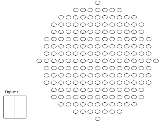
Figure 8 Polarization status map
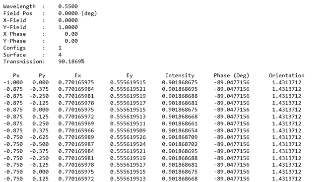
Figure 9 Data list of polarization status in full pupil
It's important to note that the specifics of the Abbe roof prism geometry and material properties will depend on your specific design requirements. Additionally, familiarity with Zemax's user interface and functions, such as .POB template, Polarization Pupil Map, is essential for efficient modeling and analysis.
