SIwave is a powerful signal-integrity (SI), power-integrity (PI), and electromagnetic-interference (EMI) analysis tool for printed circuit boards (PCBs). It includes multiple solvers that support design, verification, optimization, and debugging workflows. One of SIwave’s strongest capabilities is its collection of intelligent wizards. With only a few inputs, users can set up complex PCB analyses involving dozens of structures in a very short time, with a very low risk of setup errors.
The DDR Wizard is one of these tools. It enables users to configure a complete DDR interface on a PCB quickly and consistently.
DDR Signal Overview
A DDR interface consists of DQ, DQS, and DDR_CLK signals:
-
DQ signals are single-ended data lines. Each DDR memory device typically uses 8 DQ lines, which transfer data bytes in parallel.
-
DQS signals are differential strobe signals that provide timing reference for the DQ lines. Each DDR memory device has its own dedicated DQS pair.
-
DDR_CLK is also a differential signal, but it is shared across all DDR memory devices. It connects the CPU (or controller) to the DDR devices in a fly-by (series) topology.
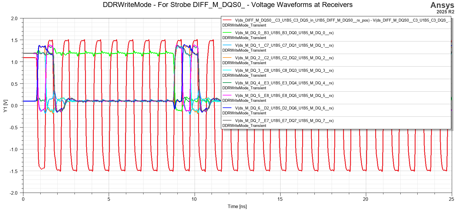
Read and Write Timing
-
In write mode (CPU → memory), the CPU drives the DQS signal, and the DQ data is centered half a unit interval (UI) away from the clock edges.
-
In read mode (memory → CPU), the memory device drives the DQS signal, and the DQ data is aligned with the rising and falling edges of DQS.
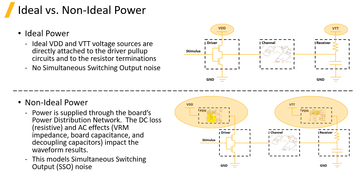
Termination Scheme
Both DQ and DQS signals use on-die termination (ODT) with a termination resistance (Rtt) connected to Vtt.
-
Vtt is equal to half of the signal voltage.
-
ODT is enabled at the receiver and disabled at the transmitter, depending on the direction of data transfer.
DDR Standards
DDR memory exists in multiple generations and categories, including:
-
DDR1, DDR2, DDR3, DDR4, DDR5
-
Low-Power DDR (LPDDR)
-
Graphics DDR (GDDR)
-
High-Bandwidth Memory (HBM)
While these standards differ in speed and electrical limits, their fundamental signaling concepts are very similar.
Setting Up DDR Analysis in SIwave
-
Launch SIwave and import the PCB layout.
SIwave supports IPC-2581 and ODB++ formats.
For Altium designs, the Ansys Altium Add-In can be used to convert the layout into an EDB format.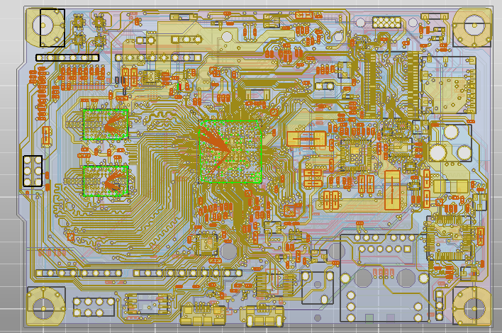
-
Identify differential pairs.
Open the Differential Pair panel and use Auto Identify to detect all differential signals.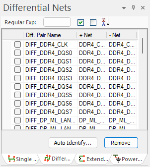
-
Navigate to the Simulation panel and launch the DDR Wizard.

-
Enter the required parameters, for example:
-
Data Type: DDR4
-
Speed: 2133 MT/s
-
Command Rate: 1T
Click Auto Identify, and the wizard will automatically search the PCB, identify all DDR-related nets, and assign them correctly.
-

DDR Wizard Settings
By opening the Settings panel, users can view all standard-defined electrical limits. These values can be modified if custom constraints are required.

Next page is the IBIS setup
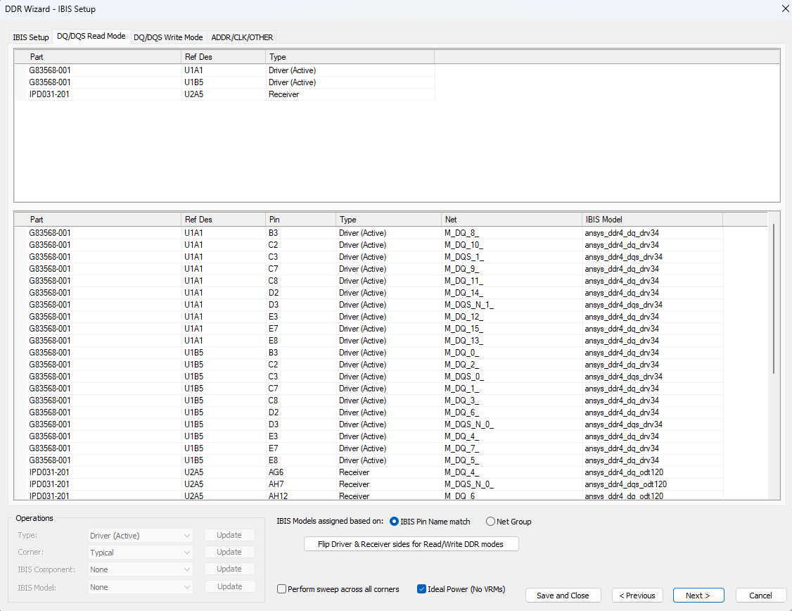
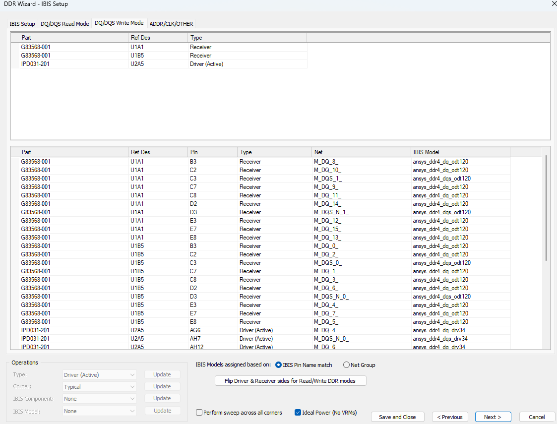
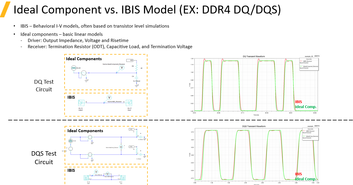
IBIS and Simulation Setup
In the next steps, the wizard allows configuration of the IBIS models.
-
Use the SSS (Simplified Switching Source) model if IBIS models are not available and the goal is to evaluate general interconnect behavior or S-parameter response.
-
Use Touchstone models if circuit generation and time-domain eye post-processing are not required.
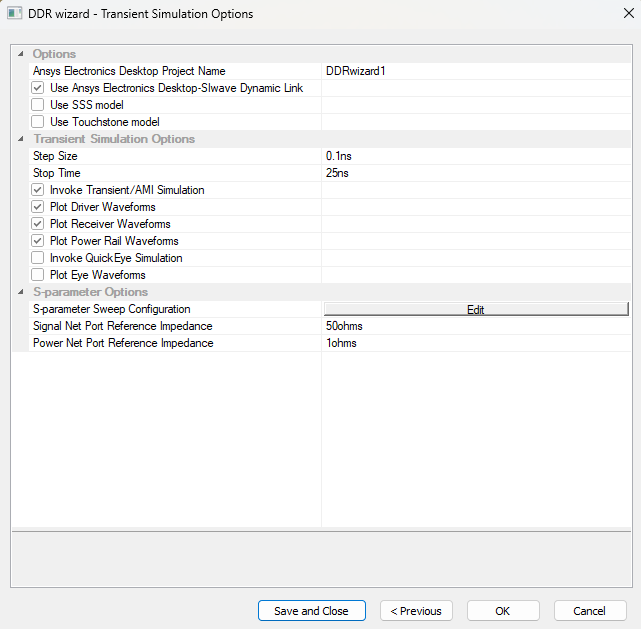
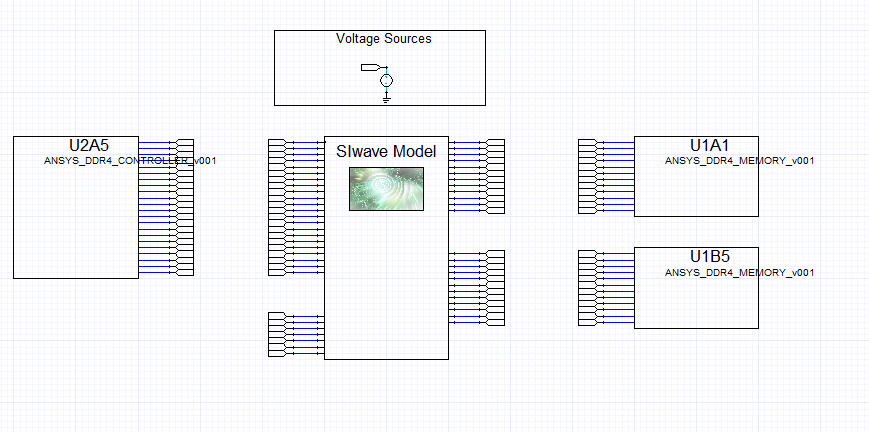
SIwave then automatically generates a complete circuit model for post-processing and analysis.
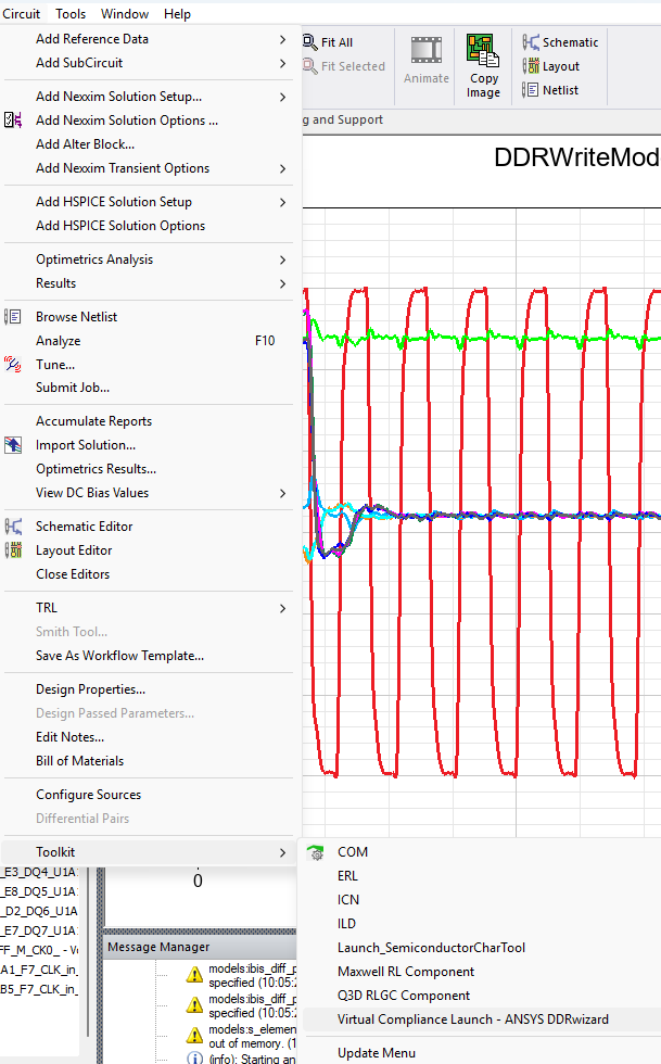
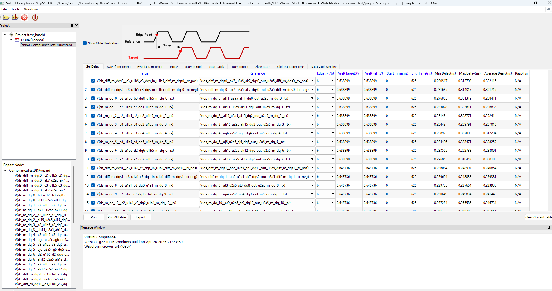
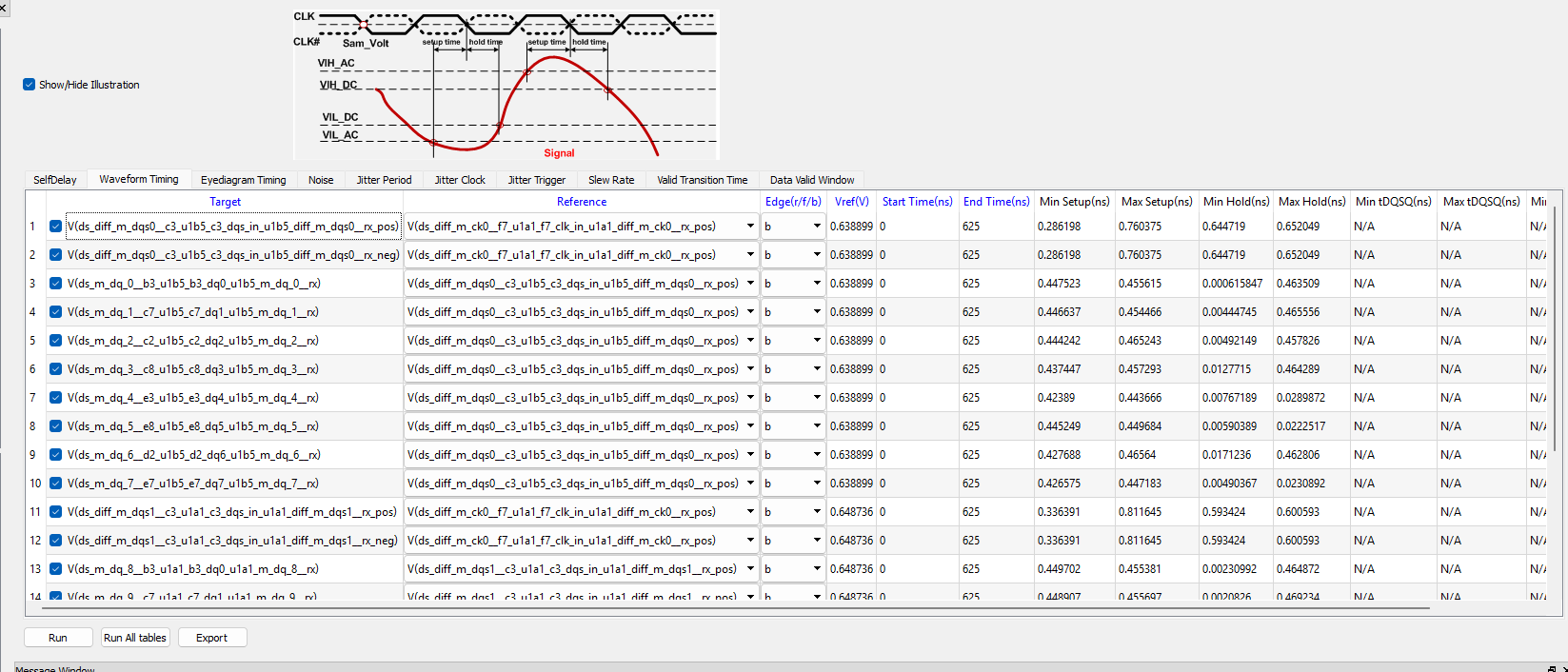
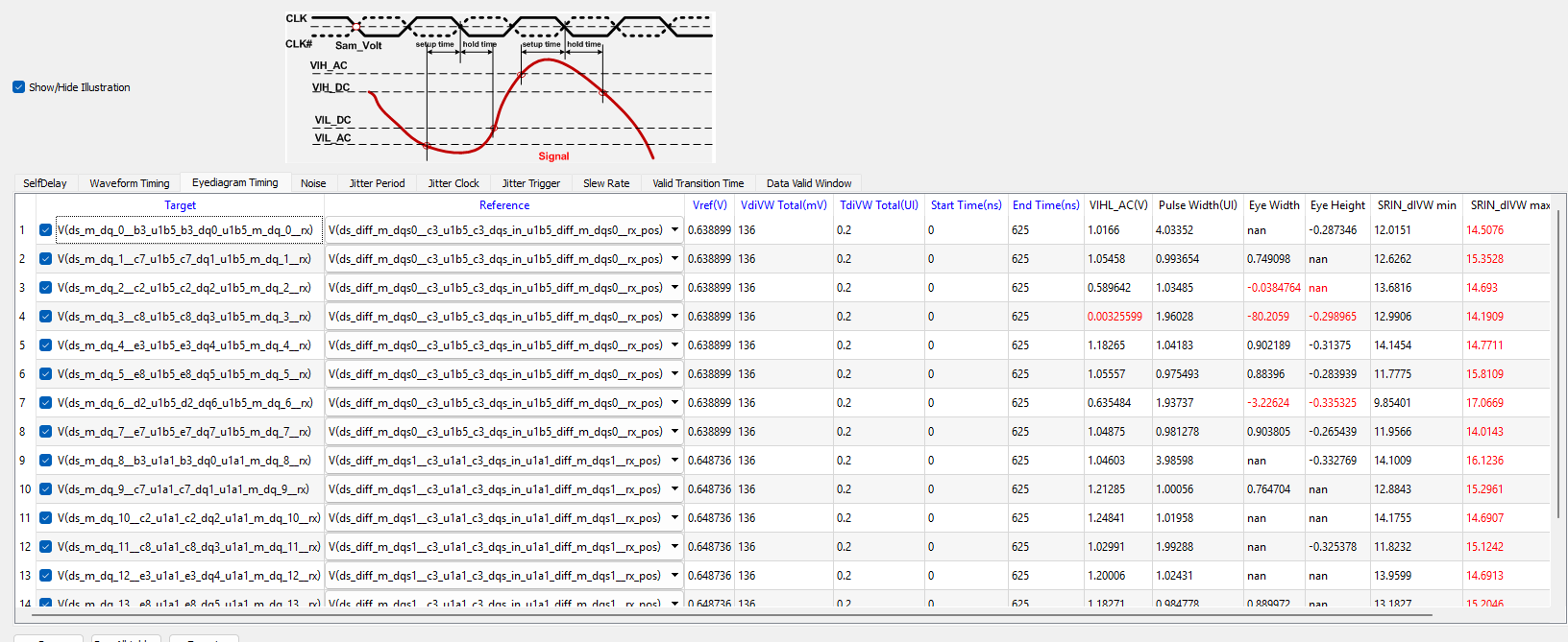
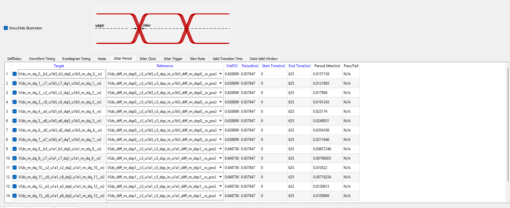
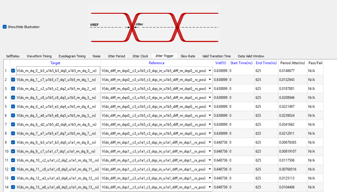
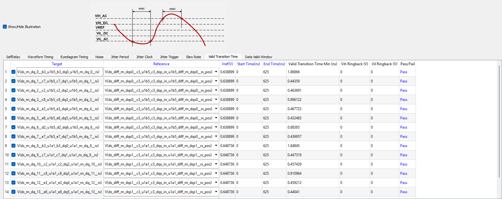
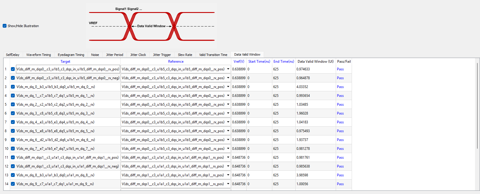
DDR Compliance Analysis
To perform compliance checks, launch the DDR Compliance Kit from:
Tools → Toolkit → Virtual Compliance Launch
Each compliance section includes:
-
A graphical explanation of the measured parameter
-
A pass/fail indicator based on the selected DDR standard


Additional Notes
Further definitions and explanations are available from the Ansys DDRwizard documentation.