
Stray light refers to unwanted light that enters an optical system or imaging device and contributes to the overall background illumination. This light can arise from various sources and reflections within the optical system, and it may have a detrimental effect on image quality and system performance.
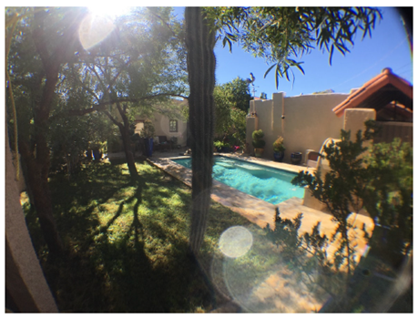
Figure 1 Instance of ghost Image
The impact of stray light on an optical system depends on the application. In imaging systems, stray light can reduce image contrast, introduce artifacts, and degrade overall image quality. In scientific instruments, it can affect the accuracy of measurements and observations. Therefore, optical designers take great care to analyze and mitigate stray light effects during the design and optimization phases.
Stray light often contributes to the formation of ghost images. When light scatters or reflects within the optical system, it may eventually lead to the creation of unwanted ghost images. Figure 1 illustrates impact of ghost image in a sunshine environment.
Stray light can be mitigated through careful optical design. The use of anti-reflective coatings, baffles, stops, and other design features helps minimize reflections and scattering that contribute to stray light and ghosting.
Here offers a case to conduct stay light analysis in Zemax Nonsequential mode. It is a Cooke lens with 3 pieces glasses. The optical structure is shown in Figure 2. It is a type of photographic lens design, namely Cooke Triplet, which is characterized by its use of three lens elements arranged in a specific configuration to reduce optical aberrations and produce high-quality images. The structure consists three lens elements: a positive (convex) lens, a negative (concave) lens, and a positive lens.
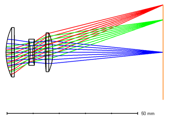
Figure 2 Cooke lens structure with 3 pieces of glass
Cooke lenses played a significant role in the development of cinematography, and variations of the Cooke triplet design have been used in cinema lenses. The design's ability to provide sharp images made it suitable for filmmaking. The case here integrates three field settings in angle, which are 0, 14 and 20 degrees.
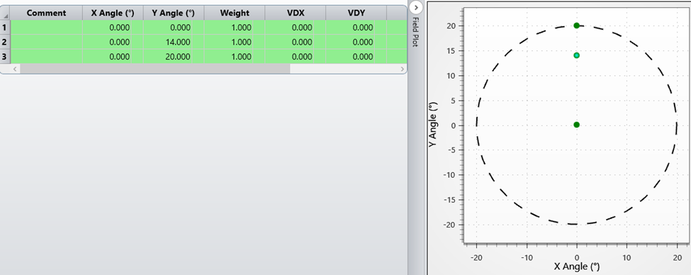
Figure 3 Fields of the Cooke lens
The stray light analysis is based on ray path analysis, which is conducted in the non-sequential (NSQ) mode. Here we convert the structure into NSQ mode using the built-in function of Zemax with default settings. The converted structure in NSQ is shown in Figure 4. The three fields defined in the sequential mode are presented with three source objects and three detector objects.
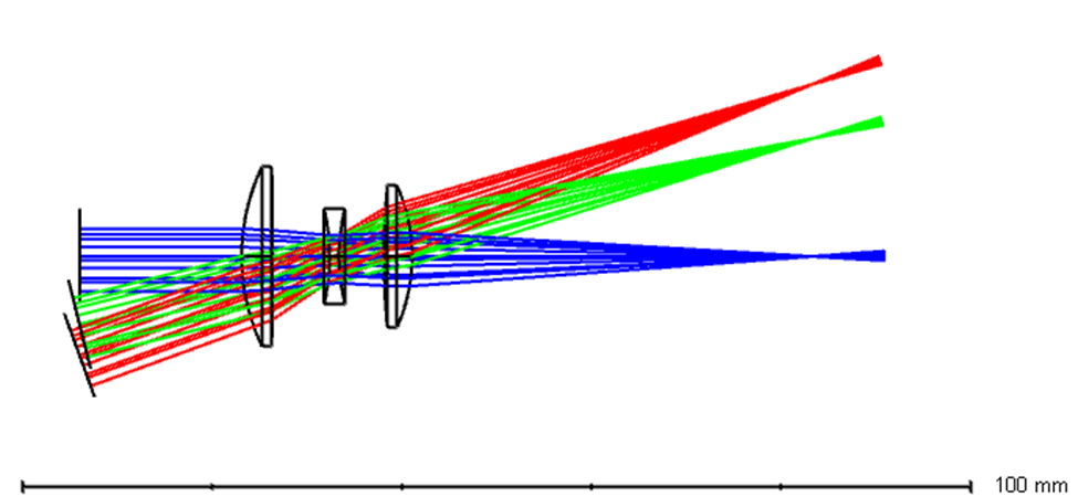
Figure 4 NSQ model of the 3-piece Cooke lens
To illustrate the stray light energy distribution at the detector plane, a rectangular shaped detector, with a size of 60 mm x 60 mm, is placed there, as below. Pixel numbers are set to 300 x 300 for this detector, as shown in Figure 5.
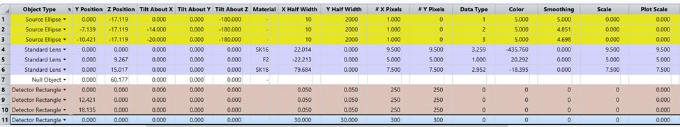
Figure 5 NSQ component editor for stray light analysis
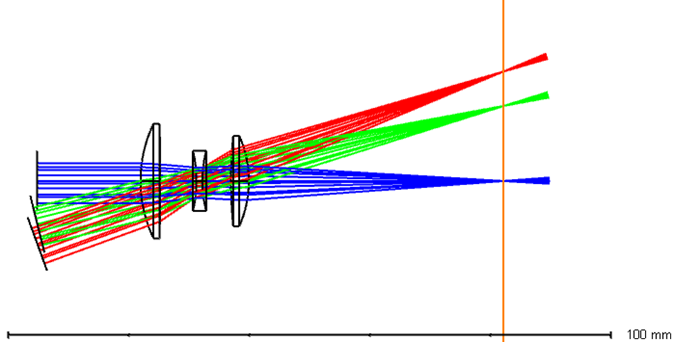
Figure 6 NSQ model with an added rectangular detector
Each of the three sources are allocated to 2000 rays and trace the ray with scattering and splitting NSQ rays, and save the ray database as a ZRD file, as below:
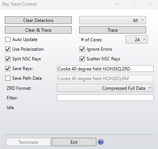
Figure 7 NSC ray tracing setting
The incoherence irradiance at the added detector from the tracing is shown in Figure 7. It can be seen that the stray light irradiance in the center of the view (small blue dots). Those are the stray light energy that projected in the detector plane. Some further actions are needed to identify and reduce them.
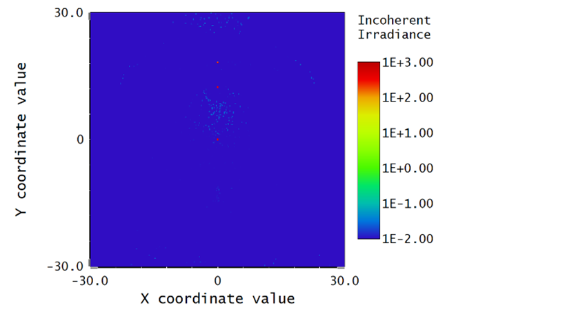
Figure 8 Incoherence radiance at the added detector
We can apply a filter string: G0&H11, in the 3D layout. G0 means ghost light segment from any subject of the lens combination. H11 suggests light segment hitting object 11, which is the added rectangular detector. The minimum relative ray intensity is set as 3E-3, meaning that the lowest threshold of segment energy shown in the layout.
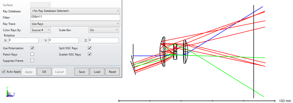
Figure 9 Typical stray light layout
To trace the stray light contribution of each element, we need the “Path Analysis” feature of Zemax, which is only accessible in Premium or higher version. Figure 10 shows path analysis of the ray tracing result above. It can be identified that the light is largely reversed back at object 5 (path #s 7,8,9) and 6 (Path #s 10,11,12). Thus Anti-reflection (AR) coating is added to both surfaces of the two elements, as shown in Figure 11.
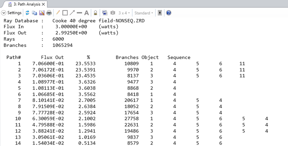
Figure 10 Ray path analysis to identify critical stray light paths
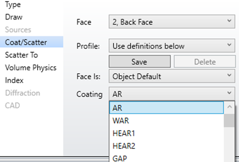
Figure 11 Apply AR coating to both surfaces of objects 5 and 6
When tracing with the same setting of Figure 7, a much cleaner layout at detector is shown, as below in Figure 12.
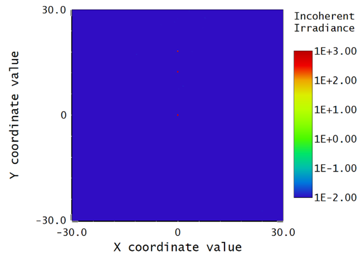
Figure 12 Incoherence radiance at the detector plane after adding AR coating to critical elements
The overall stray light analysis process can be complex. Each stay light path contribution can be significantly reduced after being identified and coated. Make adjustments to the optical system, coatings, or other parameters based on the results and iterate until the desired performance is achieved. Zemax provides a comprehensive platform for optical design and analysis, and the specific steps and options may vary based on the version of Zemax being used.
