LED stands for "Light Emitting Diode," which is a semiconductor device that emits light when an electric current passes through it. LED lighting is known for its energy efficiency, long lifespan, and versatility in applications ranging from residential lighting to automotive and industrial uses. OSRAM is a well-known manufacturer of lighting solutions, including LED lighting products. OSRAM offers a wide range of LED products, including LED bulbs, LED fixtures, LED strips, and LED modules.
Zemax OpticStudio provides extensive libraries of optical components and materials, including various types of light sources, lenses, mirrors, and detectors. It also includes manufacturer-specific libraries for LED products from companies like OSRAM. Here is an example of using OSRAM LED to build a specific illumination model, as in the preview below.
The LED unit we are using is OSRAM Rayfile KW DELSS2. The file of this product can be found officially below. The file to be downloaded for Zemax is “rayfile_KW_DELSS2_CC_20210218_Zemax.zip”.
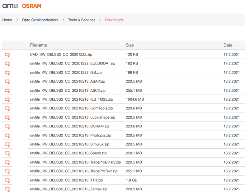 After decompressing, a bunch of files which carry multiple information of this LED are in a folder, shown below.
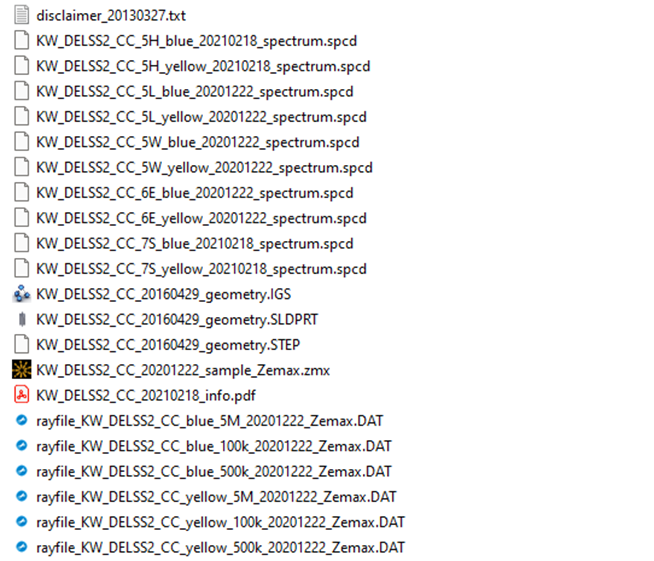
The “KW_DELSS2_CC_20210218_info.pdf” is a high level introduction of the LED mode. Most important information includes position of global coordinate origin vs. package, general properties of the rayfile, luminous intensity and near field illuminance simulated in Zemax, radiometric and photometric spectra curves.
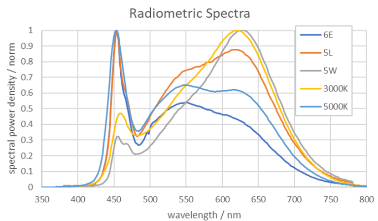
Radiometric spectra provide information about the radiant flux or power of light at each wavelength. This is typically measured in watts per square meter per nanometer (W/m²/nm). Radiometric measurements are concerned with the total power emitted by a light source, without considering how the human eye perceives it. This means that radiometric spectra provide a complete picture of the electromagnetic radiation emitted by a light source across the entire spectrum, including wavelengths that may not be visible to the human eye.
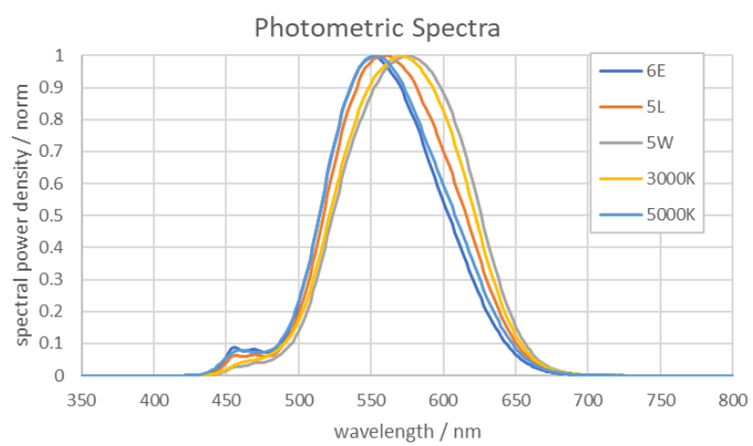
Photometry, on the other hand, is the measurement of light as perceived by the human eye. Photometric spectra take into account the sensitivity of the human eye to different wavelengths of light, as described by the photopic response curve. This response curve represents the eye's sensitivity to light under bright conditions. Photometric measurements are weighted according to this response curve, resulting in units such as lumens (lm), which represent the total luminous flux emitted by a light source. Photometric spectra provide information about the brightness or intensity of light at each wavelength as perceived by the human eye.
The spectrum of the LED represented in this rayfile package has two local maxima due to the specific generation principle of white light used for this LED type. The slope in the blue wavelength range has narrow width and a peak wavelength around 454 nm, the slope in the yellow wavelength range has a wide distribution with a peak wavelength around 590-650 nm depending on the LED type.
Due to the different angular characteristics of the rays referring to the blue and yellow parts of the spectrum a separation of the ray model in two parts is recommended. Therefore, two rayfiles have been delivered with this rayfile package. One rayfile for the blue and one rayfile for the yellow part of the spectrum. Both rayfiles have the same global coordinate origin and must be placed in a simulation at exactly the same x-,y-,z-coordinates. To use the rayfiles in a simulation the user has to consider the following points:
- "blue" and "yellow" rayfile must be placed at the same x-,y-,z-coordinates
- simulation to be done simultaneously for the two raysets, like two overlapping sources
- Luminous flux contributions of both rayfiles must be chosen, e.g. by integration of the slope of the spectrum for the referring LED color bin.
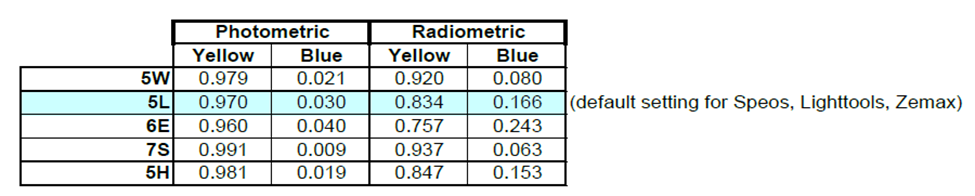
The luminous flux ratio between yellow and blue depends on the spectrum and is therefore slightly different for the different chromaticity coordinate groups. The table below summarizes typical ratios resulting from the integration of the blue and yellow part of the spectra:
The provided rayfiles for Zemax are in binary format. In addition a sample file is included in the package showing the recommended settings and placement of rayfiles and CAD model. The sample file contains the typical Luminous flux of the LED and the typical spectrum. Additionally, the radiometric color spectrum is included as *.spcd file in the package. The specific interactions with Zemax are described below:
- Rayfiles: Copy “rayfile_KW_DELSS2_CC_blue_5M_20201222_Zemax.DAT”, “rayfile_KW_DELSS2_CC_yellow_5M_20201222_Zemax.DAT” into “Documents\Zemax\Objects\Sources\Source Files”.
- Spectrum files: Suppose 6500K LED (temperature code 6E) is used, Copy “KW_DELSS2_CC_6E_blue_20201222_spectrum.spcd”, “KW_DELSS2_CC_6E_yellow_20201222_spectrum.spcd” into “Documents\Zemax\Objects\Sources\Spectrum Files”.
- CAD files: Copy “KW_DELSS2_CC_20160429_geometry.STEP” into “Documents\Zemax\Objects\CAD Files”.
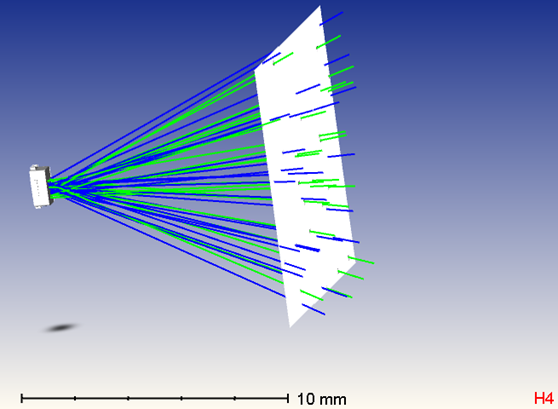
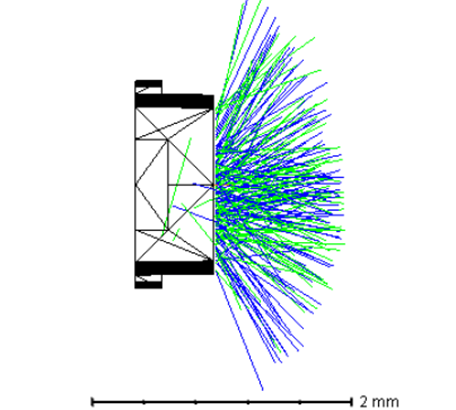
In Zemax, import two source files (.DAT) of blue and yellow, then specify the corresponding spectrum file, as Objects 1 and below. Then insert another CAD part object and choose the CAD model of this LED, as Object 3 below. Lastly set a Detector Color with 100 x 100 pixels away from the LED.
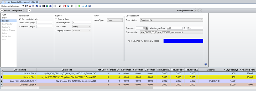
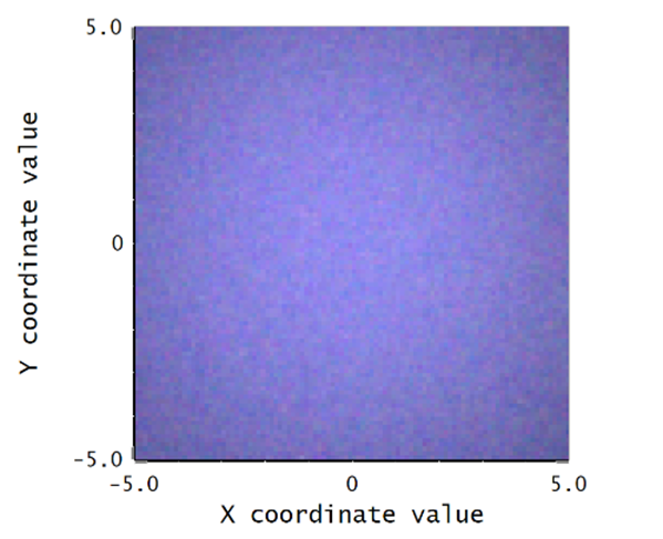
The LED model is presented below, with a quick real color illumination pattern in the detector. The tristimulus pixelwise data can be retrieved in the Text tab of the detector presentation.