In this blog I show how a Magnetic Coupler can be modeled and analyzed in Ansys Maxwell using the Magnetostatic solver to see how the torque and magnetic flux density distribution varies with mechanical angle. We can vary and sweep any “non-time-varying” input parameter to analyze how torque or force is varied vs mechanical angle in the Magnetostatic solver. This model could easily be converted to an axial flux motor by replacing the stator permanent magnets with electromagnets.
Analyzing power performance would require “Time” and this is achieved with the Magnetic Transient solver.
GEOMETRY
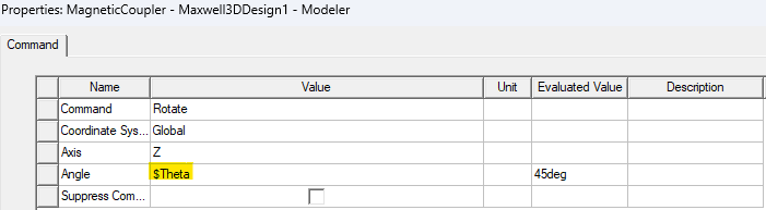
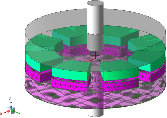
RMxprt was used to automatically create a model of a 3D axial flux motor and this model was modified using a few simple modifications to create this Magnetic Coupler model. The rotor was selected and a "Rotate" operation was assigned and an angle variable "$Theta" was used in the definition.
PARAMETERS
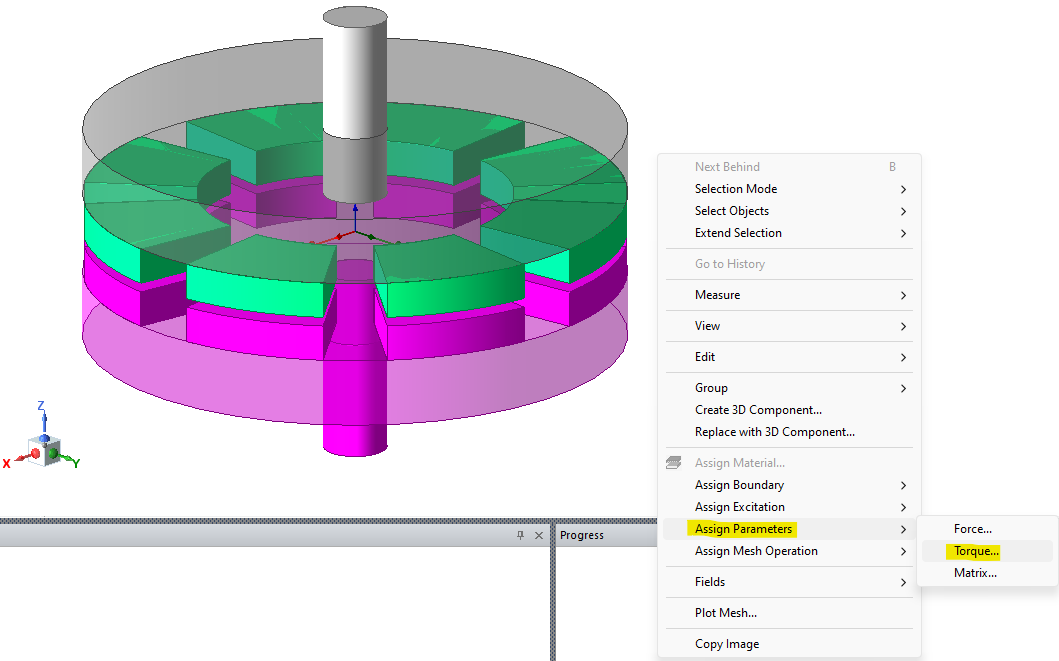
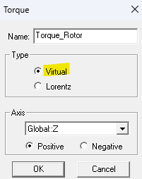
Select the rotor, right click, go to "Assign Parameters", select "Torque", and choose virtual torque since we are computing torque on permanent magnets. Lorentz torque is used for electromagnets.
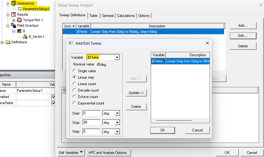
VARIABLES & OPTIMETRICS
Right click on "Optimetrics", add a "Parametric", and add a "Sweep". The definition for "$Theta" is shown below. The solver will solve at every angle in the sweep and allow how the Torque parameter changes with this angle.
MAGNETS
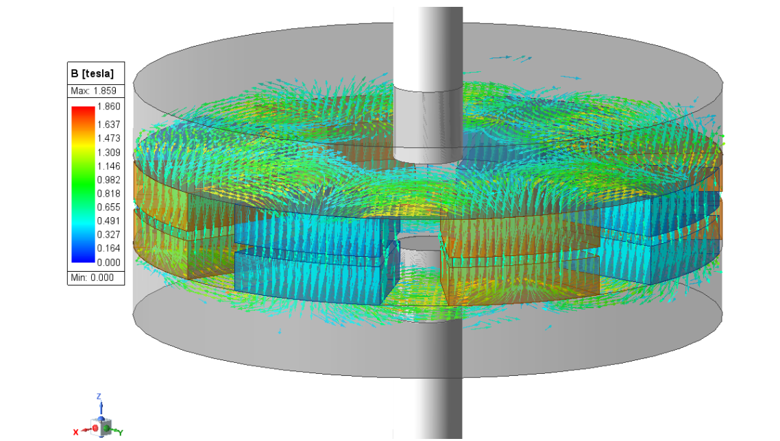
In this model the B Field of the magnets either point along the positive z direction or in the negative z direction. Two materials for the permanent magnets are used and in one material the z component is positive and in the other material the z component is negative. The different magnets are positioned in the rotor and stator around their core in an alternating manner.
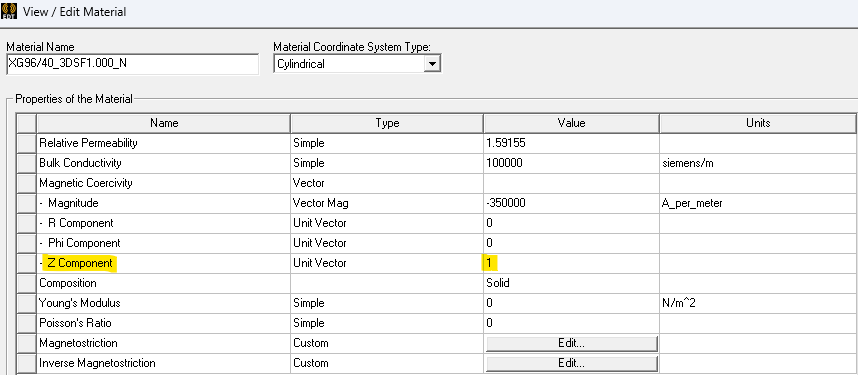
B Field pointing along the positive z direction.

B Field pointing along the negative z direction.
MESH
The mesh in a Magnetic Transient model requires Cylindrical Gap Treatment and Band assignments to model motion and power performance. However, the Magnetostatic solver does not require these assignments since motion is not being modeled. We are just analyzing how torque varies with mechanical angle using an angle parameter.
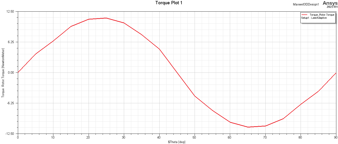
RESULTS
Below is an animation of the B Field distribution and a plot of the rotor torque vs mechanical angle defined with the angle variable and sweep definition. When like magnets are aligned in the rotor and stator, north and south of the magnets are facing each other and experience an attractive force. The opposite is true when opposing magnets are aligned. Torque is in one direction one region (when pulling attracted magnets away from each and pushing towards repulsing magnets toward each other), and torque is an another direction in another region (pulling repulsing magnets away from each other and pushing attracting magnets toward each other. These regions vary periodically between stator magnets around the stator.
OZEN ENGINEERING YOUTUBE VIDEO
ABOUT OZEN ENGINEERING INC.
Ozen Engineering is a leading provider of Ansys solutions, catering to a diverse range of industries with a specialization in electronics, semiconductor, biomedical, healthcare, aerospace and automotive applications. Our team delivers personalized solutions to optimize product design and performance by seamlessly integrating Ansys simulation into the product development process. As an elite channel partner of Ansys, we provide best-in-class software tools, consulting, training, mentoring, and technical support.
Contact us to learn about our simulation capability and request a demonstration for us to show you how we can help you with your engineering projects. Ozen Engineering Inc is an Ansys Elite Channel Partner, and we provide training to use Ansys tools, offer consulting services, and sell Ansys software packages.
Visit our website
Give us a call
Send us a message