ANSYS MAXWELL: PARAMETERIZED AXIAL FLUX MOTOR
Hello, Axial Flux Motor Fans:
In this blog I discuss how to parameterize Axial Flux Motors in Ansys Maxwell so that you are able to analyze various designs and obtain the optimized design for your application. The topics covered are,
- Geometry Parameterization
- Symmetry
- Motor Control Circuit
- Excitation Polarity
- Mesh Operations
- Analysis Setup
- Post Processing Analysis
Geometry Parameterization
There are really two categories of variables to create (1) radial, and (2) elevation. The key to model parameterization is to
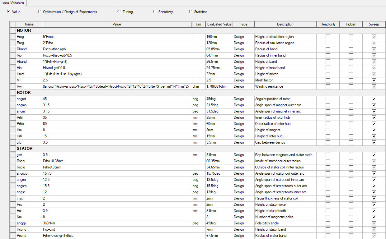
- Create variables for all geometric quantities and express variables in terms of other variables as much as possible. For example, outer radiuses can be expressed of inner radius and thickness. Below is the list of geometric variables used to parameterize the model in the example of this blog.
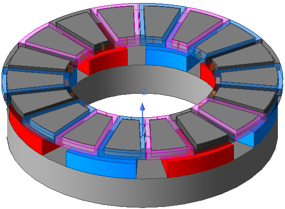
- Define the radial and elevation directions. In this example, the xy plane of the global coordinate system is used as a reference plane for elevating all objects and the z direction is along the motor axis. The workflow used to create the geometry is place the bottom surface of each object on the xy plane (perpendicular to the motor axis, parallel to the radial direction) and then elevate (move) the objects in the direction of the motor axis to the required position.
Symmetry
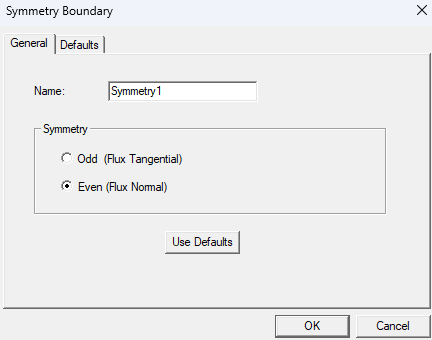
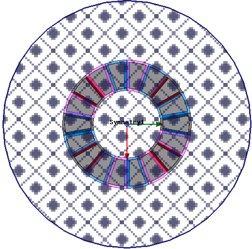
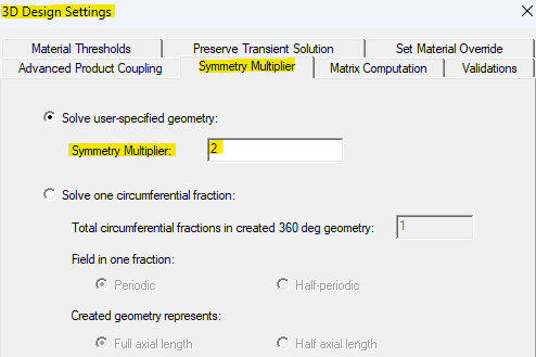
This Axial Flux Motor is a Double Rotor type and a half symmetry model is used. The symmetry plane cuts through the center of the stator coils and "Even" symmetry is selected since the magnetic flux is perpendicular (Normal) to this plane. Go to the 3D design settings and ensure the Symmetry Multiplier is applied with the correct value. In a future blog (coming soon) I will discuss using the "Solve one circumferential fraction" Symmetry Multiplier option.

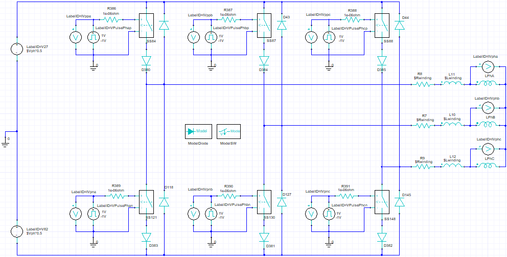
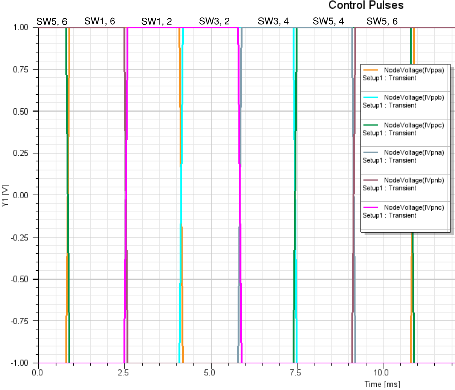
Motor Control Circuit: Three Phase Square Wave Voltage, Brushless DC
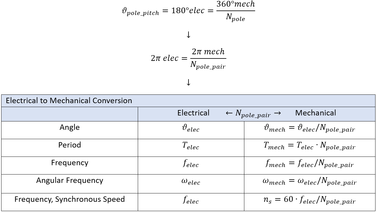
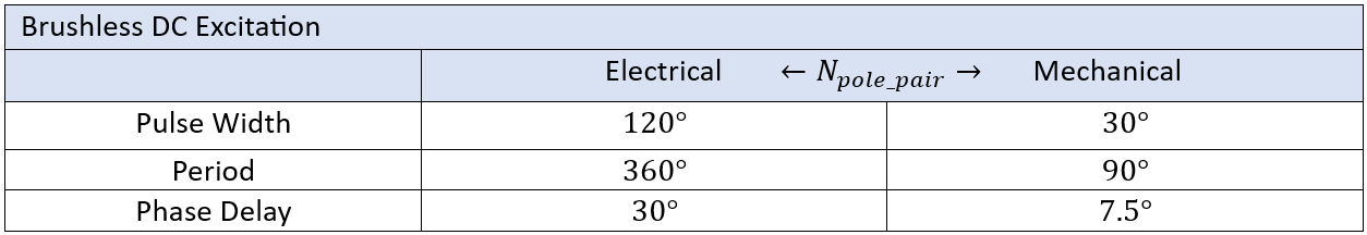
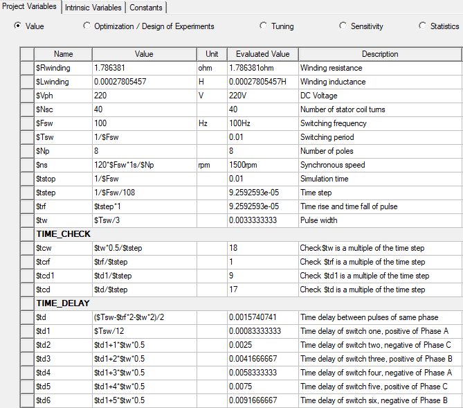
Below are the relationships between electrical and mechanical angles, frequencies, and temporal periods. Switches are controlled based on TIME. If POS (position) is used to control the switches then mechanical angles must be used as inputs and this is converted to arc length using variables Kle and Kang (not covered here). The pulse width, period, and phase delay are shown in the table below. Also, below is an illustration of the control pulses, control circuit schematic, and variables used.
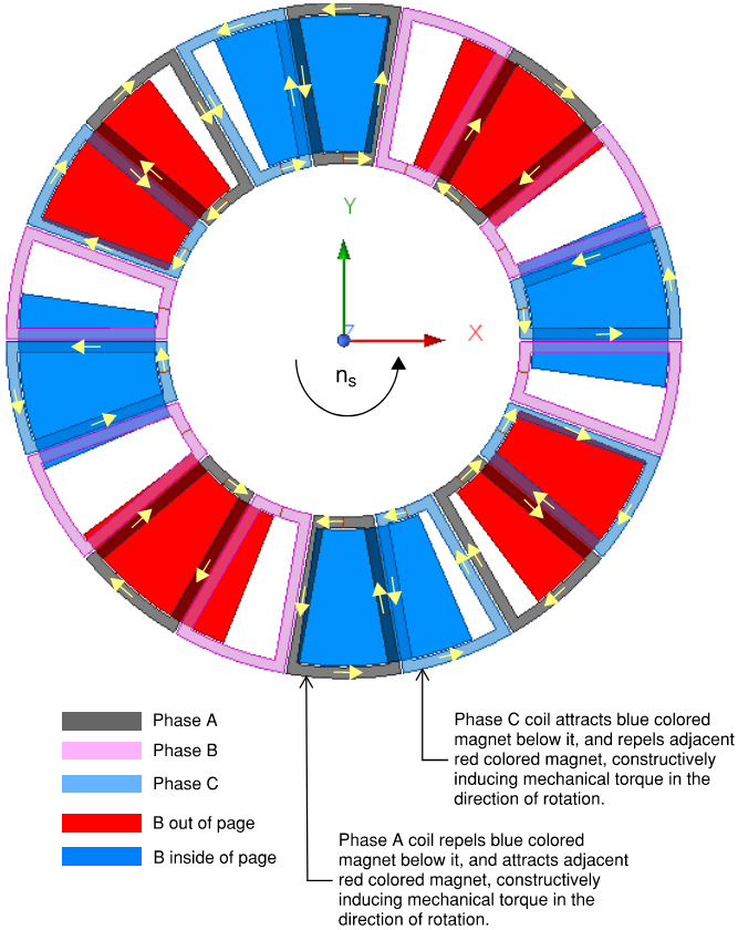
Excitation Polarity
Mechanical torque is induced on the rotor (magnets) by the stator field, and is opposite to EM torque induced on the stator coils by the magnets. When a coil is energized and in between two adjacent magnets it will attract one of the magnets and repel the other magnet. The coils should be excited such that all coils induce mechanical torques in the same direction so that rotation is developed in direction of the synchronous (stator) field. A coil does not contribute to torque when it is symmetrically aligned with a magnet. The polarity assignment of the coils should be chosen in accordance to the selected phase sequence. Also, it is important to use the correct winding resistance in an external excitation circuit. The initial position is another important parameter to consider since the windings have impedance the coils require some time to energize. Below is an illustration when Phase A and Phase C are energized, switch 1 and switch 2, are instantaneously closed.
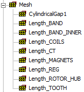
Mesh Operations
Mesh operations were applied to each object type (unique geometric entity) as shown below. Ensure that the correct units are applied for the "Max Length" size evaluated value in the properties of the mesh operation.
Analysis Setup
Right click on "Analysis" and select "Add Solution Setup". Apply a "Stop Time" (simulation time) and a "Time Step" (electrical period divided by 100 in this example). In the "Save Field' tab select "Every" and verify the final save time. In the "Solver" tab check "Smooth BH Curve".
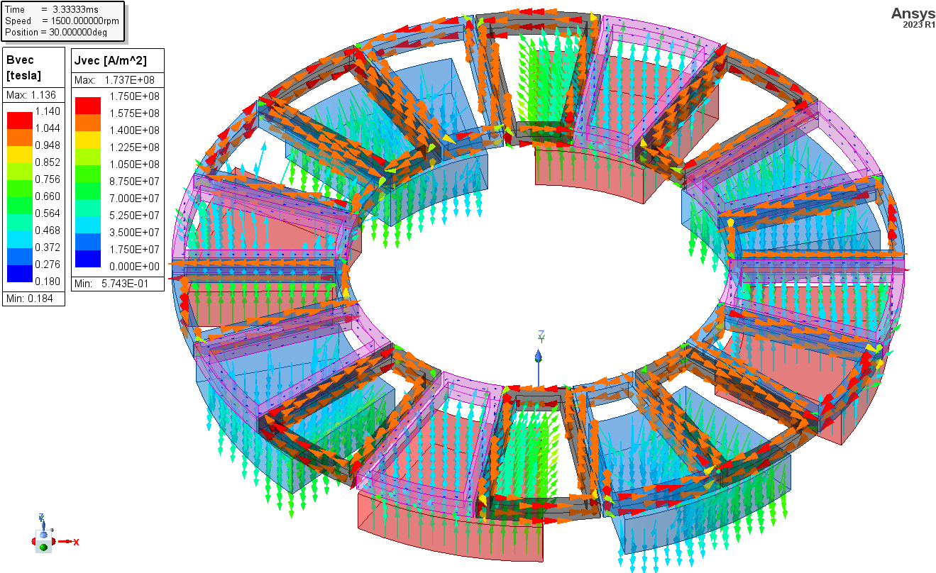
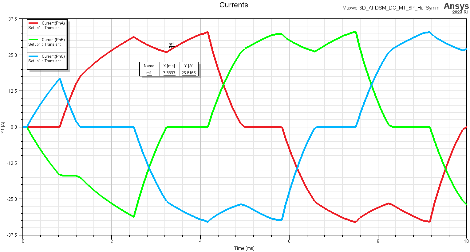
Post Processing Analysis
Below are field plots of the magnetic flux density of the magnets and the current density of the stator coils. It is clear that mechanical torque will be induced on the rotor in the positive z direction (counter clockwise from this view) based upon looking at the B field of the magnets and the current density in the stator windings. Also, the three phase currents are shown in the 1D plot below. The physics of the working principle for the torque is as explained in the "Excitation Polarity" section above.
OZEN YOUTUBE CHANNEL
ABOUT OZEN ENGINEERING INC.
Ozen Engineering is a leading provider of Ansys solutions, catering to a diverse range of industries with a specialization in electronics, semiconductor, biomedical, healthcare, aerospace and automotive applications. Our team delivers personalized solutions to optimize product design and performance by seamlessly integrating Ansys simulation into the product development process. As an elite channel partner of Ansys, we provide best-in-class software tools, consulting, training, mentoring, and technical support.
Contact us to learn about our simulation capability and request a demonstration for us to show you how we can help you with your engineering projects. Ozen Engineering Inc is an Ansys Elite Channel Partner, and we provide training to use Ansys tools, offer consulting services, and sell Ansys software packages.
Visit our website
Give us a call
Send us a message