Hello, Motor Fans:
In this blog I show how to use Motor-CAD to model the demagnetization of an Interior Permanent Magnet (IPM) motor and analyze the affects on the magnets, back EMF and torque.
IPM MOTOR TYPE
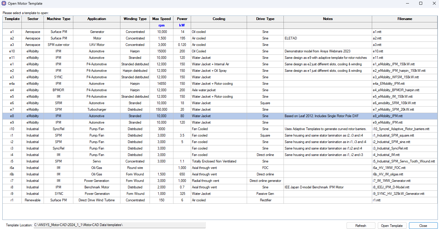
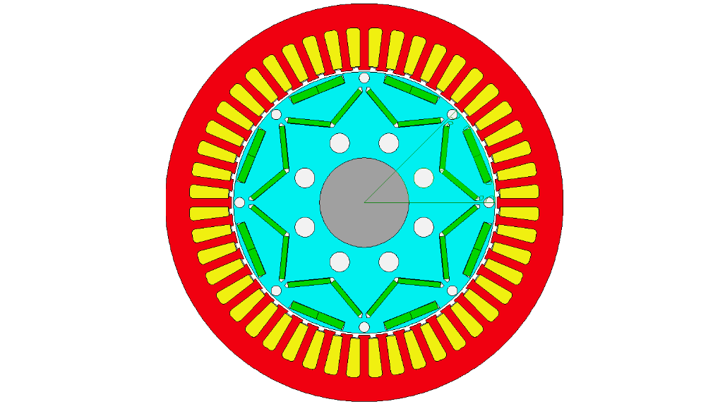
Motor-CAD has various templates to use to start a project as shown below. In this example I use the e8 template which has applications to electric vehicles. Go to File > Open Template > and choose the e8 template.
PHYSICS
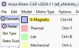
Select the Model tab and choose E-Magnetic for the physics type to model and analyze demagnetization.
The permanent magnets in this IPM motor example are N38UH, Sintered Neodymium-Iron-Boron Magnets.
Review of Demagnetization
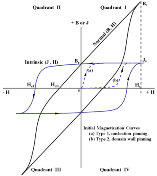
Permanent Magnet material such as N38UH are called hard magnetic material and become "Permanently" magnetized by subjecting the magnetic material to an external magnetic field produced by an electromagnet and driving the material into full saturation. The magnetic behavior of the material is described by two curves as shown below. In a permanent magnet J is one source of magnetic flux density and ![]() is the other source which can demagnetize the magnet. The equations for B and J are shown below.
is the other source which can demagnetize the magnet. The equations for B and J are shown below.
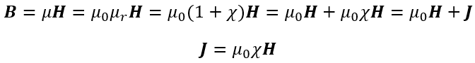
J vs H: This curve is called the intrinsic curve of the material and here J is called by different names in the literature and it is known as the magnetic polarization, or magnetic intensity, and is expressed as
B vs H: This curve is called the normal curve of the material and represents the combination of the two sources of magnetic flux density produced by the material.
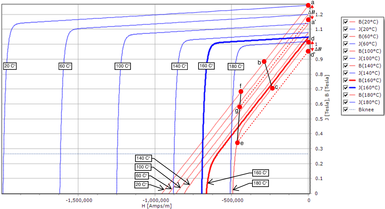
The demagnetizing curves for N38UH is shown above. The blue curves are the intrinsic curves and the red curves are the normal curves. Also, the operating temperatures for the normal curves increase from left to right, and from top to bottom. The normal curve shown in bold is for an operating temperatures of 20o C.
Demagnetization is analyzed on the second quadrant of the BH curve and the region above the knee is linear and the region below the knee is non-linear. Motor-CAD automatically detects the knee of the curve at the point that deviates by 10% from the linear region and draws a dashed horizontal line passing this point on the curve for the magnet temperature that is set. Permanent demagnetization will not occur when the motor operates in the linear region. However, demagnetization will occur after the motor enters operation in the non-linear region.
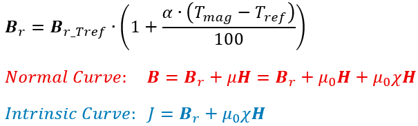
The equation used to model the temperature dependent remanent flux density is shown below, as well as the equations for the normal and intrinsic curves.
Temperature Dependence of Demagnetization
Reversible Flux Loss (linear region operation): Following motor operation along the path b, c (increasing temperature) would result in reduced magnetic flux density at point, but this magnetic flux density is reversible in the linear region and it can be restored by reversing the motor operation along path c, b (decreasing temperature).
Irreversible Flux Loss (non-linear region operation): Following motor operation along path f, e (increasing temperature) will result in magnetic flux density reduction at point b but reversing motor operation cannot be restore operation to point f since motor operation entered the non-linear region of the normal curve at 180o C. Instead of returning motor operation along path e, f (decreasing temperature), the reversed path would e, g. This result is an irreversible magnetic flux density loss.
H Field dependence of Demagnetization
Reversible Flux Loss (linear region operation): Following motor operation along path a, b (constant temperature, increasing H) would result in reduced motor flux density. This magnetic flux density loss is reversible by returning motor operation along the path b, a (same temperature, decreasing H) since motor operation is in the linear region along this path.
Irreversible Flux Loss (non-linear region operation): Following motor operation along the path d, e (constant temperature, increasing H) will result in reduced magnetic flux density. Reversing motor operation will not the path along e, d (constant temperature, decreasing H), but instead motor operation would follow the path e, d' known as a recoil path represented in the dashed line type. The magnetic flux density at point a' is lower than the value at point a, and this is an irreversible loss. An example of what can cause irreversible flux loss due to the H field is a short circuit current.
Emag SETTINGS and RESULTS
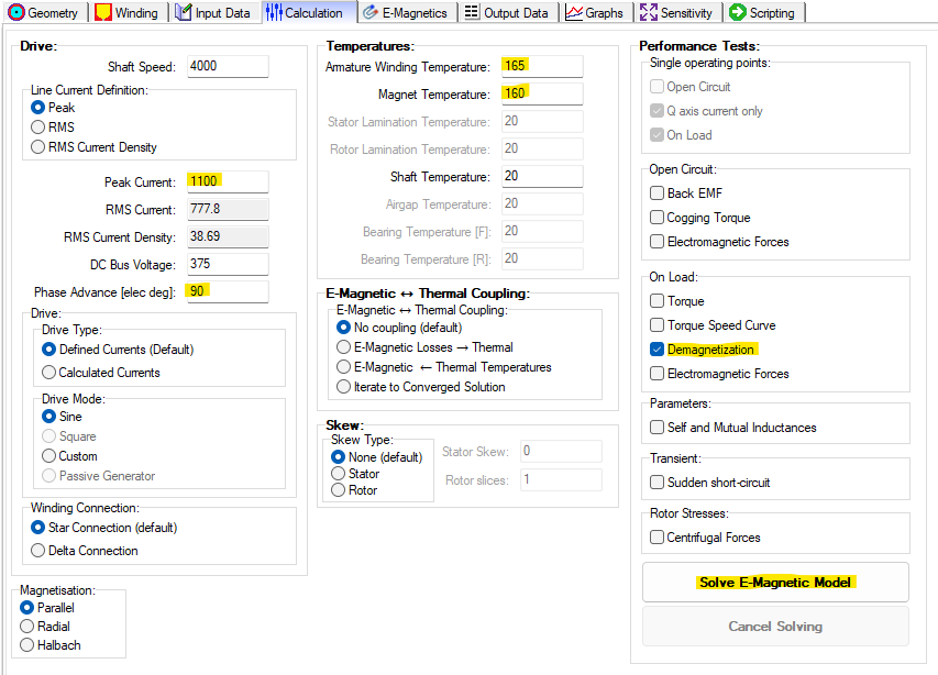
In this section we cover the settings to apply to analyze the demagnetization of the magnets, and the affects of demagnetization of on torque and back EMF. Under Performance Tests check the box for
- Demagnetization to analyze the demagnetization of the magnets.
- Torque to analyze the affects of demagnetization on torque and back EMF
The box for Demagnetization does not need to be checked if you are interested in the affects of demagnetization on torque and back EMF.
Demagnetization Affects on the Magnets
This analysis reveals how the magnets are affected by demagnetization conditions such as high current and large short circuit currents. Set the magnet temperature to the value we want to investigate demagnetization. The short circuit operating point condition can be determined by selecting the "Sudden short-circuit" Performance Test and solving the E-Magnetic Model for this initial operating point.
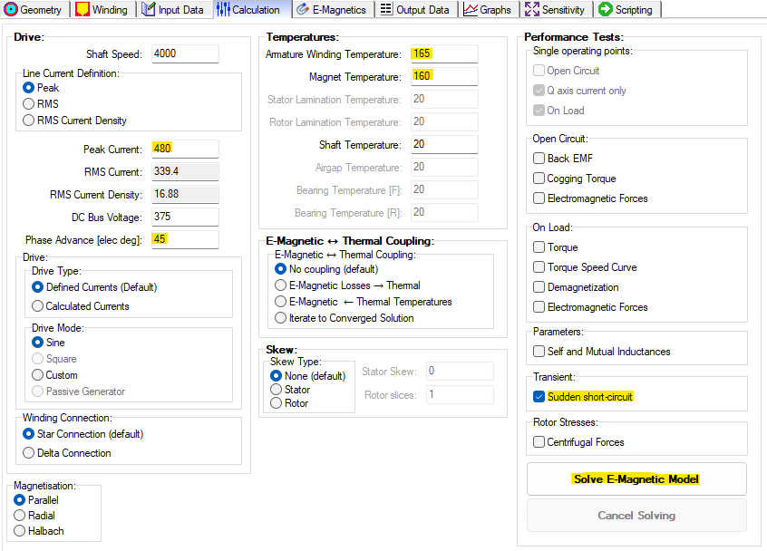
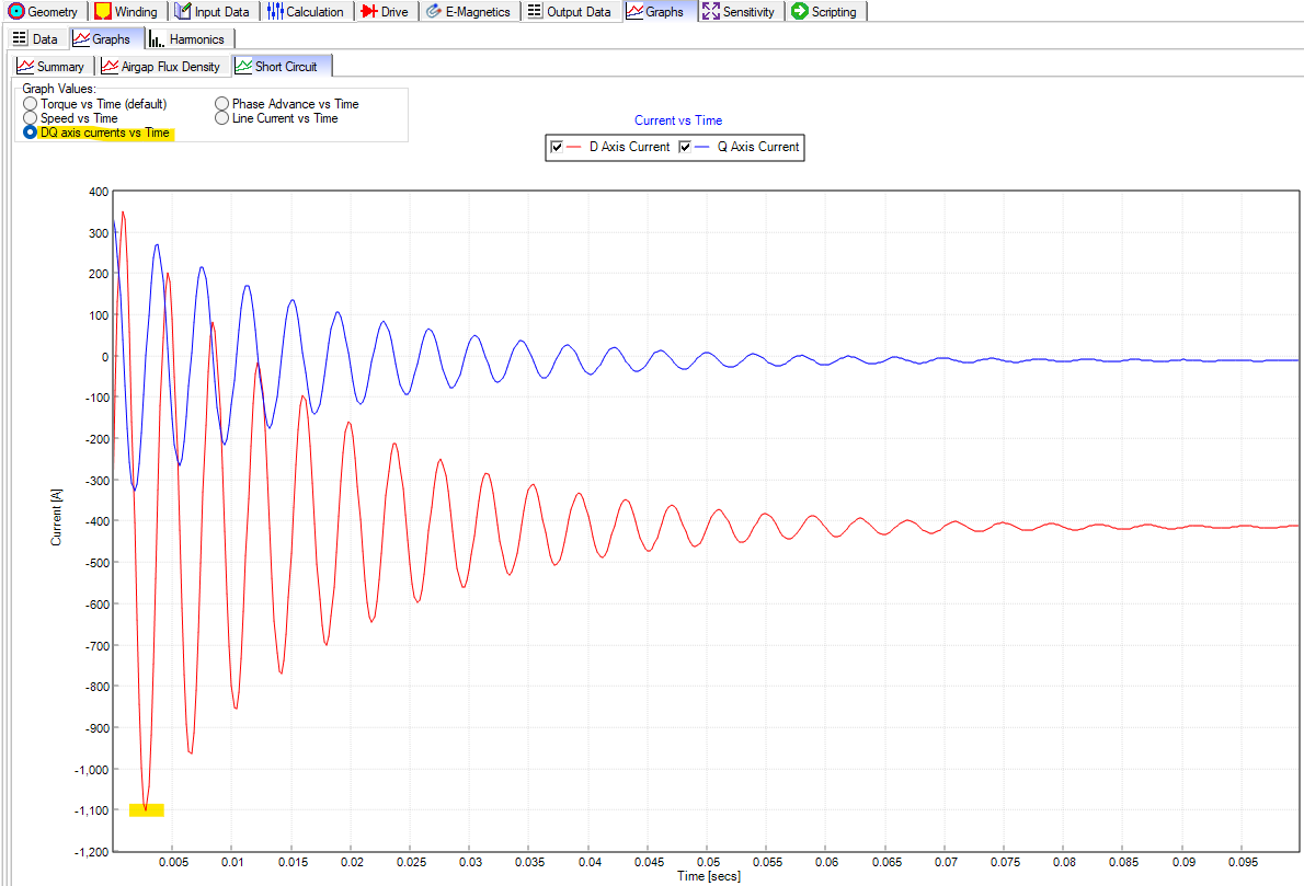
Then navigating to Graphs > Graphs > Short Circuit and then selecting DQ axis currents vs time. The short circuit value to use is the D axis current peak highlighted below.
Update the operating point in the Calculation settings for the Peak Current, and Phase Advance angle. change the Performance Test to "Demagnetization", and then solve the E-Magnetic Model.
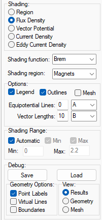
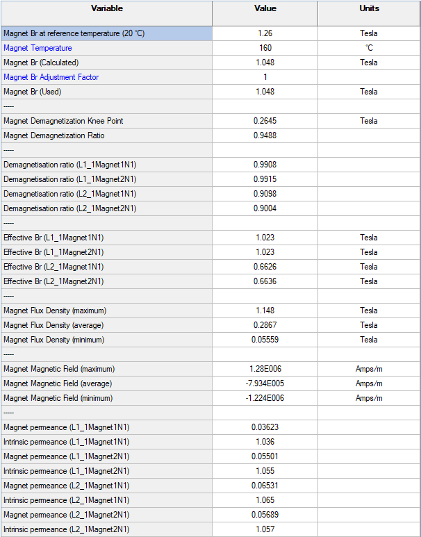
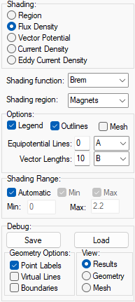
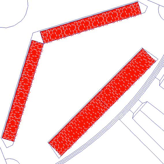
Navigate to E-Magnetics > FEA and apply the plot settings shown below. We can see that the outer layer magnets have been significantly demagnetized in magnitude and in field direction. However, the inner layer magnets experience minor demagnetization.
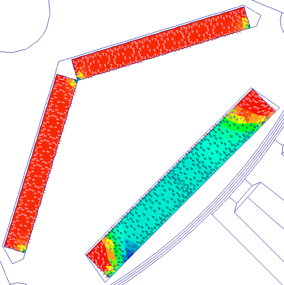
Update the Calculation settings to normal operating conditions (480 A Peak, 20o C for the magnets, and 40o C for the windings) and compare the magnets under normal condition and under demagnetization conditions. Under normal conditions in the linear region of the demagnetizing curve the magnets have uniform remanent magnetic flux density Br value equal to the value specified in the material for 20o C, and all the magnetization arrow are pointing outwards.
Demagnetization Affects on EMF
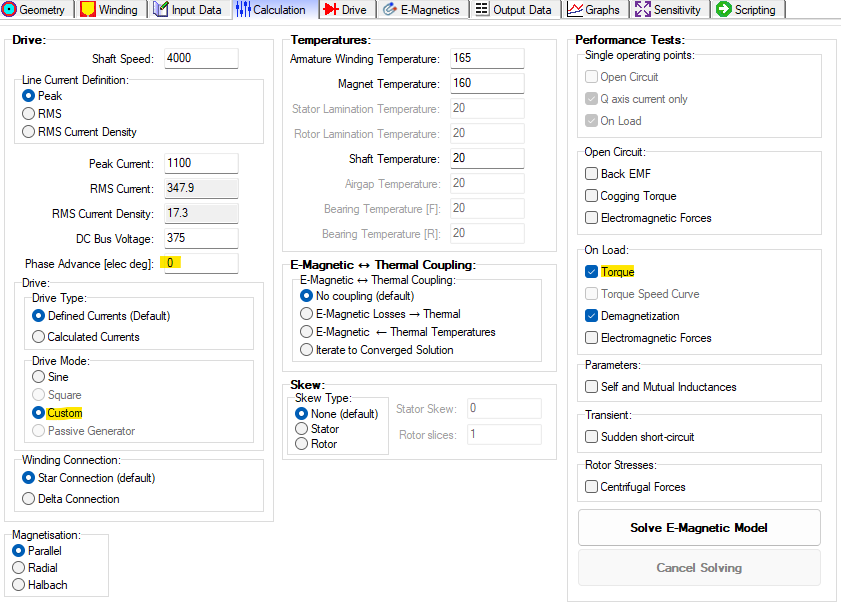
In the Calculations tab set the Drive Mode to Custom to allow to import a custom waveform for the short circuit current. The Phase Advance angle is set to 0 [elec deg] since the custom waveform we are using will not be shifted. Under Performance Tests check the box for Torque. The magnet temperature is left at 160o C, and the Armature winding temperature is left at 165o C.
Notice the Drive tab that appeared after selecting Custom for the Drive Mode. Go to the Drive tab and clear the points for the previous waveform. Select the Load Custom Waveform option and choose the short circuit waveform file you want to use. This waveform can be created in Excel and exported into a .txt file to use in Motor-CAD. Go back to the Calculations tab and select Solve E-Magnetic Model.
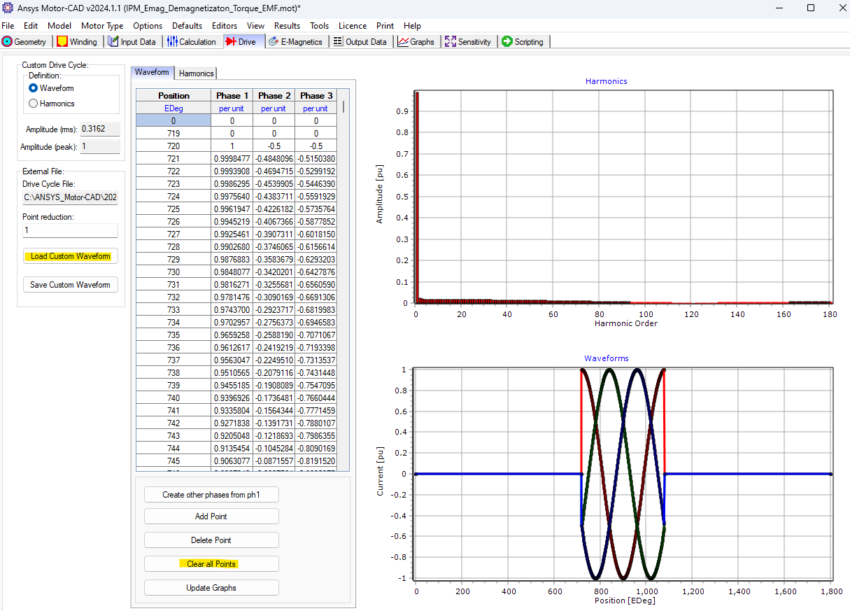
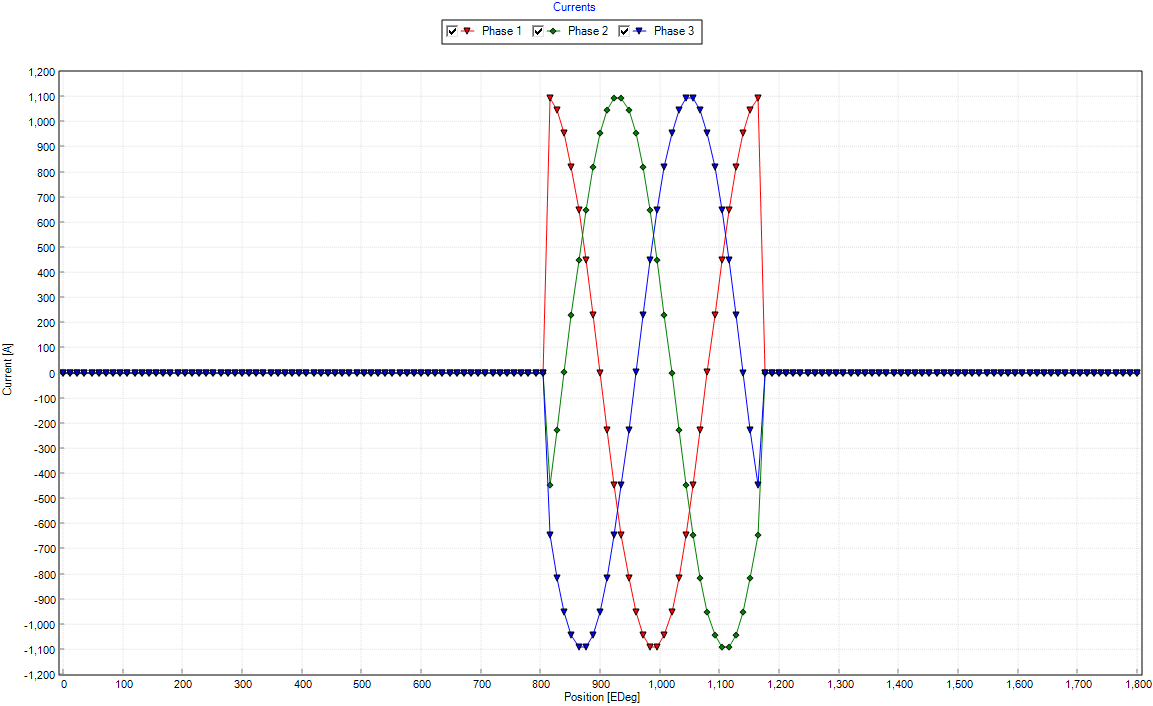
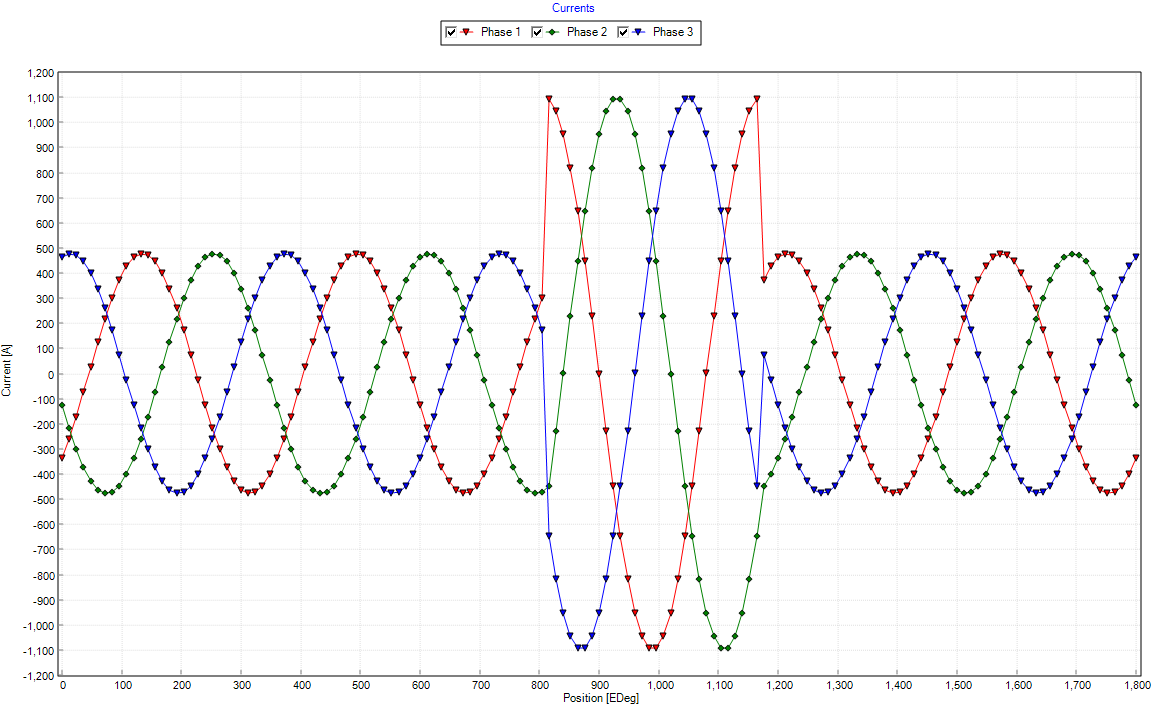
Go to Graphs tab > Graphs tab > Currents tab and see below the short circuit custom waveform we had loaded. For two electrical periods there is zero current applied, and then a short circuit current is applied for one cycle, and finally there are another two cycles of no current applied.
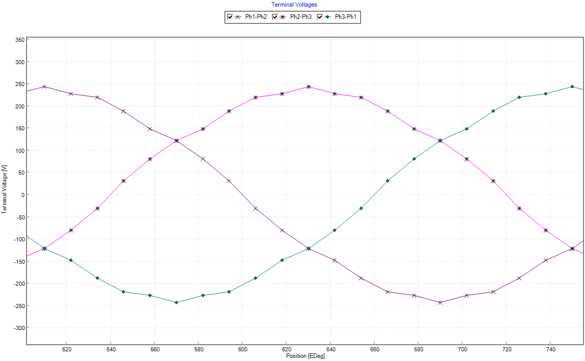
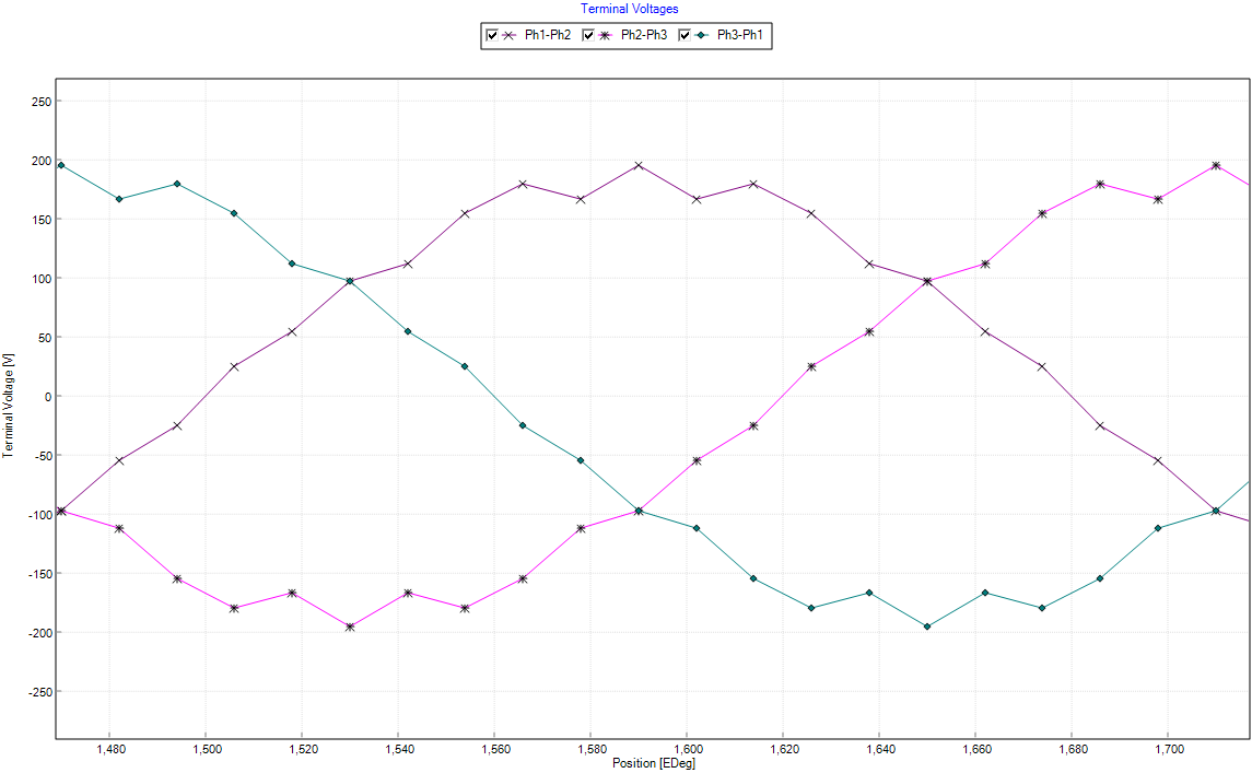
The peak line voltage before the the short circuit occurs is 244 V. However, after the short circuit current is removed the new peak line voltage reduced to 195 V, a 20% decrease, as a result of the permanent demagnetization due to heigh temperature (160o C) and high current (1100 A).
Demagnetization Affects on Torque
Follow the same procedure demonstrated above to show the affects of demagnetization on back EMF but instead apply a different custom waveform for this analysis.
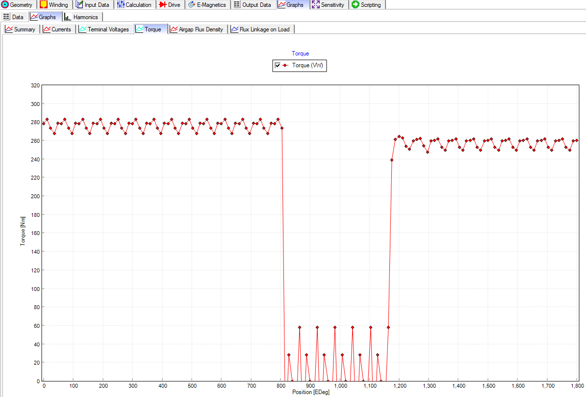
The peak torque is 283 Nm before the short circuit current occurs, and due to permanent demagnetization it reduces to 262 Nm (a 7.42% decrease) after the short circuit is removed
OZEN YOUTUBE CHANNEL
ABOUT OZEN ENGINEERING INC.
Ozen Engineering is a leading provider of Ansys solutions, catering to a diverse range of industries with a specialization in electronics, semiconductor, biomedical, healthcare, aerospace and automotive applications. Our team delivers personalized solutions to optimize product design and performance by seamlessly integrating Ansys simulation into the product development process. As an elite channel partner of Ansys, we provide best-in-class software tools, consulting, training, mentoring, and technical support.
Contact us to learn about our simulation capability and request a demonstration for us to show you how we can help you with your engineering projects. Ozen Engineering Inc is an Ansys Elite Channel Partner, and we provide training to use Ansys tools, offer consulting services, and sell Ansys software packages.
Visit our website
Give us a call
Send us a message