Hello, Electric Motor Fans:
In this blog I discuss how to use Ansys Motor-CAD to obtain torque speed curves via the LAB module. The Maximum Torque Per Amp motor control strategy is used and the constant torque region and the constant power, flux weakening region are covered. How high rotor speeds affects power output is analyzed.
MODEL
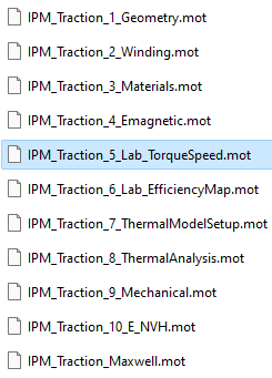
Go to the Motor-CAD installation folder via ![]()
and open the IPM_Traction_5_Lab_TorqueSpeed.mot model.
PHYSICS MODULE: LAB
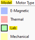
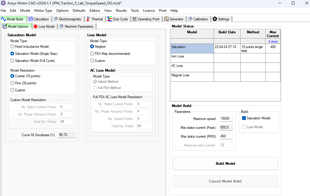
Select the Model tab and choose Lab. Go to Model Build >> Model Options. In this tab we set the Saturation Model Type and Loss Model type. Below is a description of the different model types.
Saturation Model Types
- Fixed Inductance Model - this uses the values of Ld, Lq and
 to calculate electromagnetic performance, these are assumed to be fixed and not change with current magnitude or angle.
 - Saturation Model (Single Step) - a model is built of the d and q axis flux linkages and how they vary with current magnitude and angle. These are evaluated at a single rotor position and the d/q flux linkages are assumed to be invariant of rotor position.
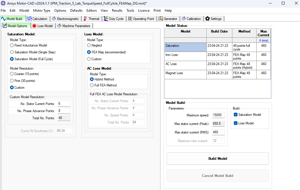
- Saturation Model (Full Cycle) - a model is built of the d and q axis flux linkages and how they vary with current magnitude and angle. These are evaluated and averaged across a number of full electrical cycles. The number of electrical cycles and points/cycle is the same as those used for the Torque calculation, defined in the E-Magnetic model under Input Data -> Settings -> Calculation.
Loss Model Types
The following loss model options are available:
- Neglect - Iron, magnet, sleeve and banding losses are neglected. Copper losses are calculated using only the DC phase resistance. This option is recommended only for initial machine sizing and design optimization as the accuracy is low.
- FEA Map - the FEA map model option is used for iron, magnet, sleeve and banding losses (if present). The DC + AC (FEA Map) option is used for the winding/copper losses. This option gives the greatest accuracy and is recommended for the majority of users.
- Custom - individual loss model options can be customized under the Loss Model tab. Recommended for advanced users only.
When the Saturation Model Resolution is set to Custom, then the number of current/phase advance points specified by the user will be used to build any FEA map loss models being used. If the model resolution is set to Coarse or Fine then 30 points will be used for any FEA map loss models (same as the Fine resolution for the saturation model).
In this blog we will build two models and compare results:
- Single Step Saturation Model Type and Neglect Loss Model Type
- Full Cycle Saturation Model Type and FEA Map Loss Model Type
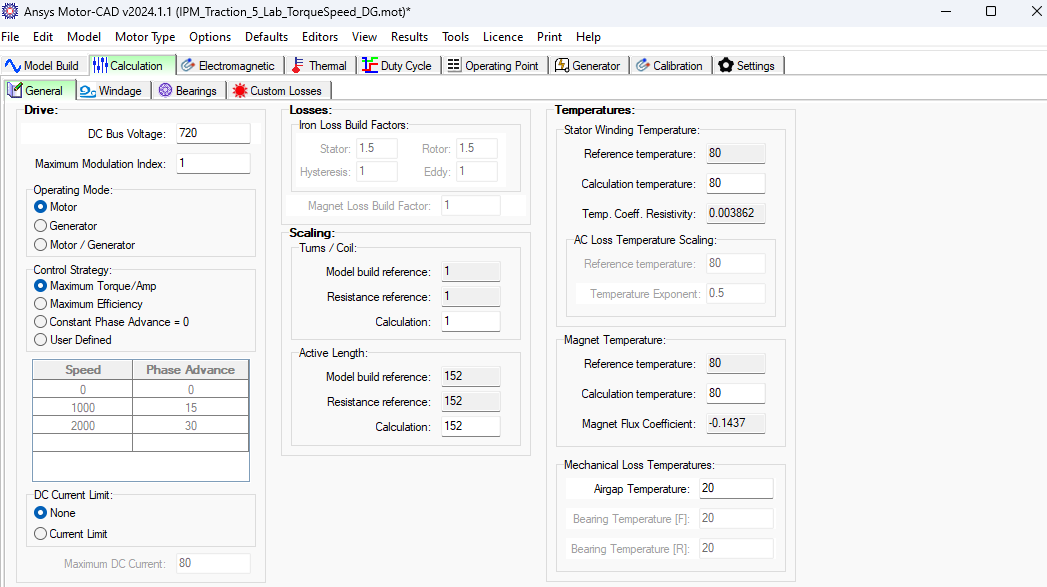
Single Step Saturation Model Type - Neglect Loss Model Type
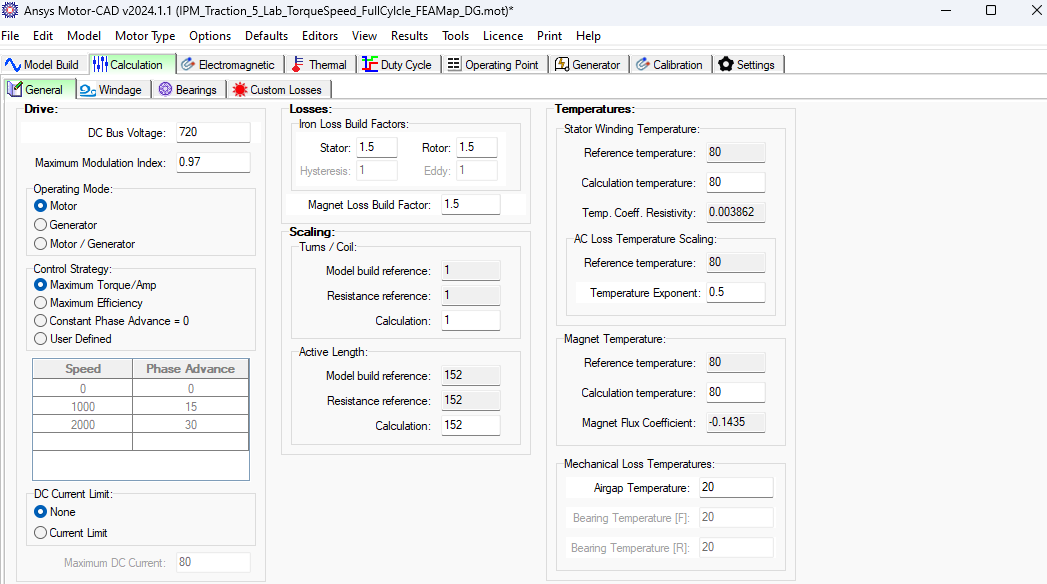
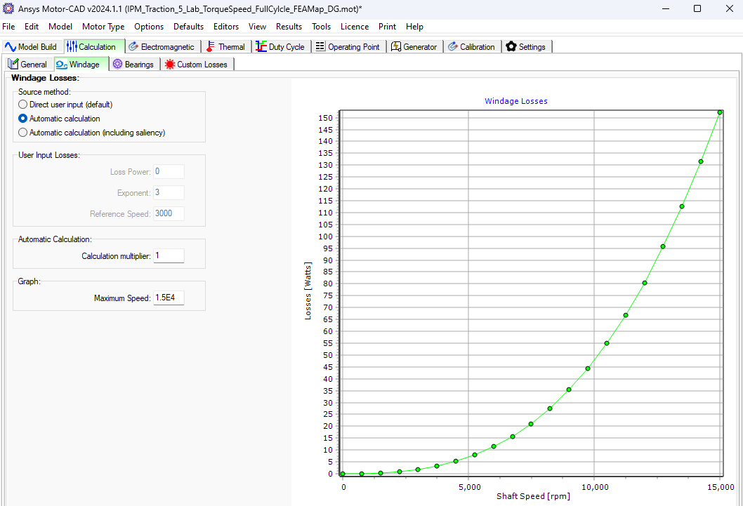
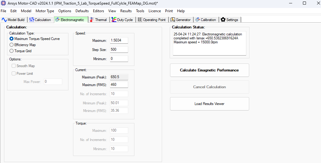
Full Cycle Saturation Model Type - FEA Map Loss Model Type
In this example AC winding losses and windage losses are included in addition to the DC windings losses. Bearing losses and custom losses may be added as desired.
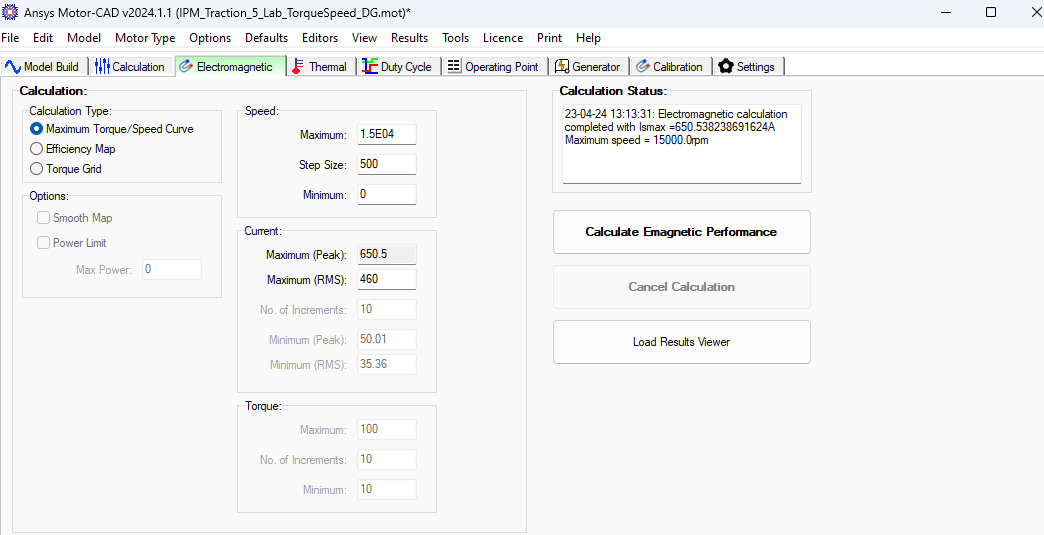
RESULTS
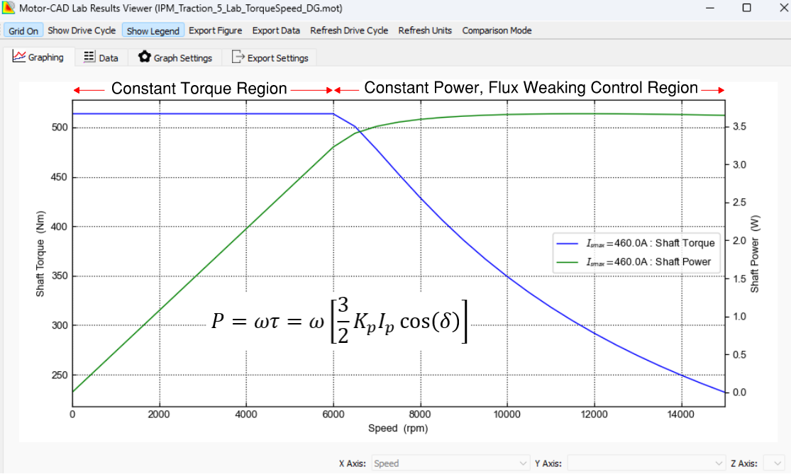
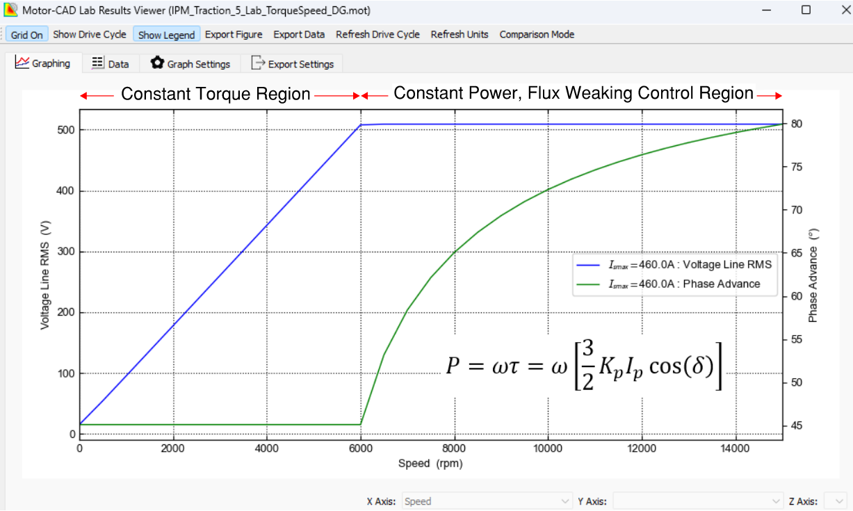
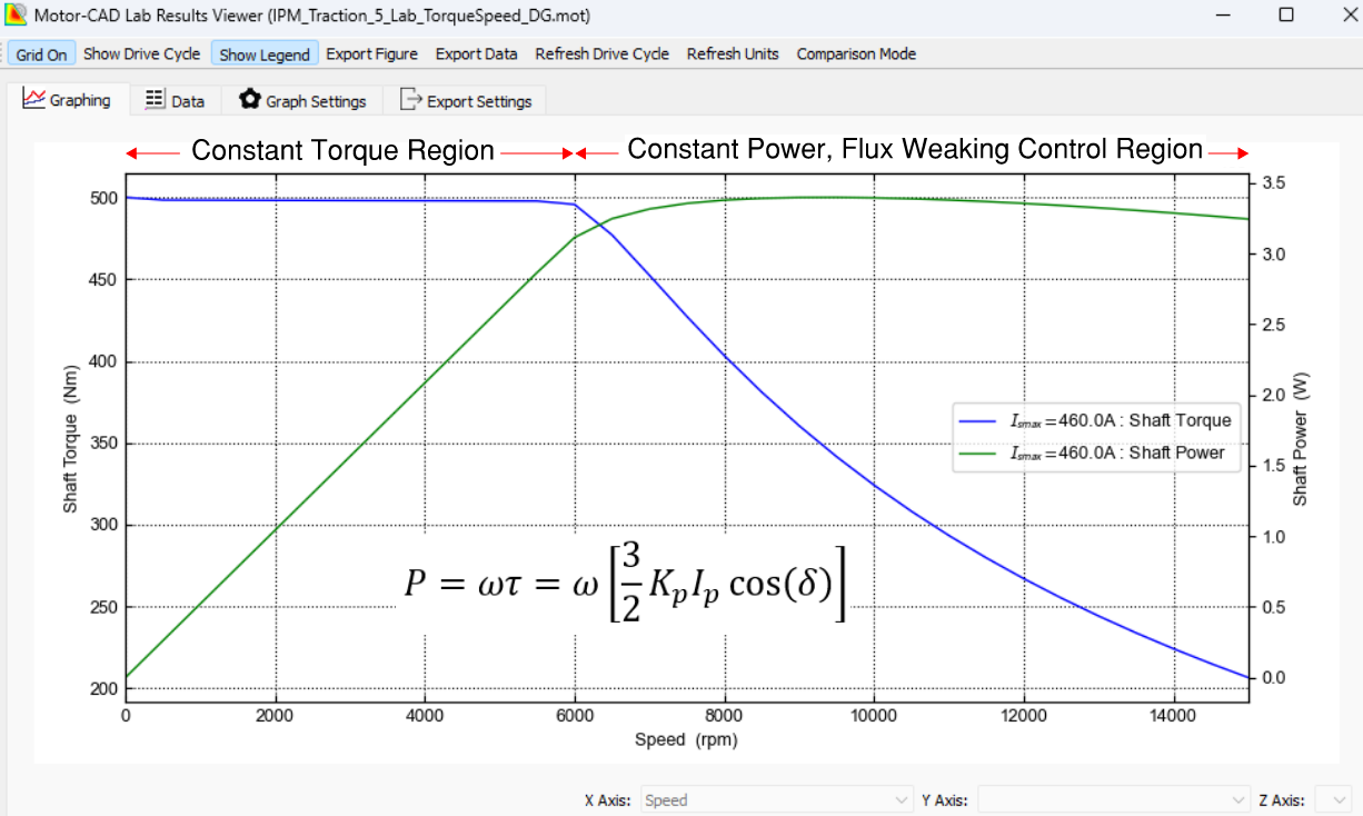
The results for the two saturation model types and loss types are discussed. Motor shaft power increases linearly with torque in the constant torque region where the phase advance angle is constant. Beyond the base speed the back emf must be reduced to avoid it exceeding the drive voltage. After the base speed is exceeded the phase advance angle increases towards 90o Elec wrt the quadrature axis, and the back EMF shape factor and ![]() both decrease and contribute to reducing the torque. Increasing the phase advance angle advances the flux produced by the stator windings to oppose the rotor magnet flux. This reduces the flux linkage and is how flux weakening is achieved. By weakening the flux linkage, the back emf and torque is reduced.
both decrease and contribute to reducing the torque. Increasing the phase advance angle advances the flux produced by the stator windings to oppose the rotor magnet flux. This reduces the flux linkage and is how flux weakening is achieved. By weakening the flux linkage, the back emf and torque is reduced.
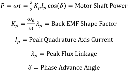
When ac losses and mechanical losses are neglected the motor shaft power is maintained at a constant level by increasing the phase advance angle, aka deviation angle, which is the angle between winding current and winding back emf phasors. As the rotor speed increases, the back EMF increases which should not exceed the drive voltage. The motor shaft power is approximately constant beyond the base speed and motor shaft power decreases slightly with increasing speed since ac losses and mechanical losses increase with speed.
Single Step Saturation Model Type - Neglect Loss Model Type
Full Cycle Saturation Model Type - FEA Map Loss Model Type
OZEN ENGINEERING YOUTUBE VIDEO
ABOUT OZEN ENGINEERING INC.
Ozen Engineering is a leading provider of Ansys solutions, catering to a diverse range of industries with a specialization in electronics, semiconductor, biomedical, healthcare, aerospace and automotive applications. Our team delivers personalized solutions to optimize product design and performance by seamlessly integrating Ansys simulation into the product development process. As an elite channel partner of Ansys, we provide best-in-class software tools, consulting, training, mentoring, and technical support.
Contact us to learn about our simulation capability and request a demonstration for us to show you how we can help you with your engineering projects. Ozen Engineering Inc is an Ansys Elite Channel Partner, and we provide training to use Ansys tools, offer consulting services, and sell Ansys software packages.
Visit our website
Give us a call
Send us a message