In this blog I give an overview of 3PH Induction Motor Design with Ansys RMxprt, an industry based motor template design tool. RMxprt allows designers to quickly and easily obtain analytical results of the Electromagnetic physics. After initial design and the first stage of optimization in RMxprt, the design can be automatically created in Maxwell for FEM analysis in 2D or 3D and to obtain Multiphysics (Electromagnetic, Thermal, Mechanical) results to achieve the ultimate, optimal design for your particular application. Also, in Maxwell an industry based machine can be modified to achieve a unique, innovative design, and in this workflow many modelling steps would be already completed.
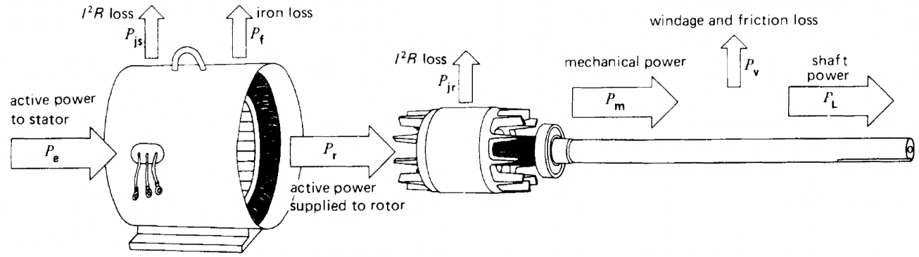
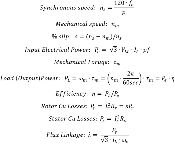
3PH INDUCTION MOTOR WORKING PRINCIPLE & FUNDAMENTAL EQUATIONS
STARTING A RMxprt DESIGN
To start a RMxprt design, you can go to the AEDT ribbon, choose one of two ways:
1. select the "Maxwell" drop down and select RMxprt and start from nothing, or
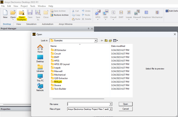
2. select "Open Examples", select the "RMxprt" folder, select 1 of 20 motor types, and select a design modify.
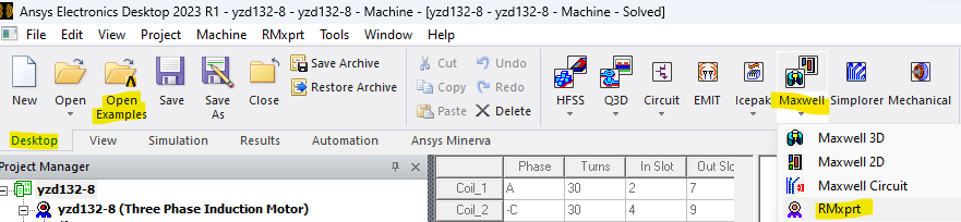
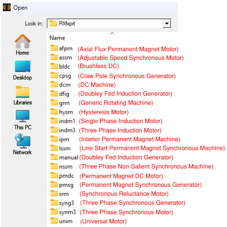
Select "Open Examples", and select the "RMxprt" folder.
The 20 motor types are shown below. The three phase induction motor is selected for this blog.
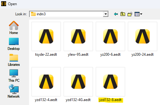
The yzd132-8 design is selected inside the "indm3" folder.
VARIABLE PARAMETERIZATION AND OPTIMETRICS
It is good modelling practice to define variables (parametrize) design values in the beginning to be able to easily sweep these variables in the design optimization process. These variables can be used in expressions to set parameterized values for other quantities.
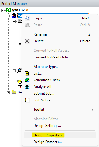
Fig. 1: Right click the design name and select "Design Properties".
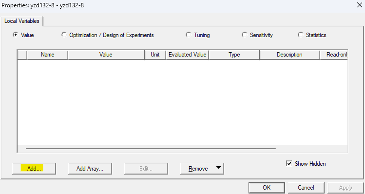
Fig. 2: Select "Add" to add a variable.
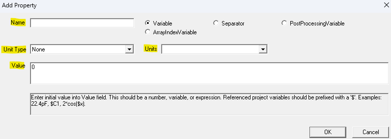
Fig. 3: Define the name (no spaces), unit type, unit prefix, and value of the variable.
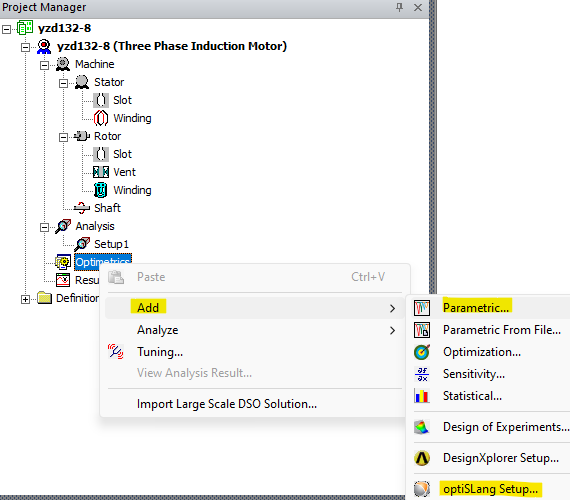
Fig. 4: Right click on "Optimetrics" and select "Add", then select "Parametric" to sweep a variable, or select "OptiSLang Setup" to setup specialized studies and obtain efficiency maps or other specialized results.
DESIGN PROPERTIES
Below are the views of the design properties of the machine, stator, and rotor. It is easy to find design settings and modify the design as desired for your particular application.
MACHINE
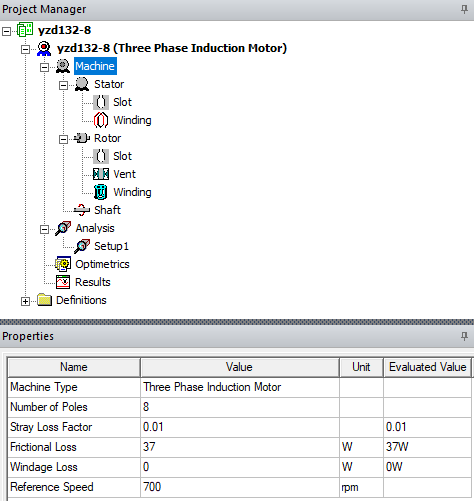
Fig. 5: Enter the nameplate information of the machine.
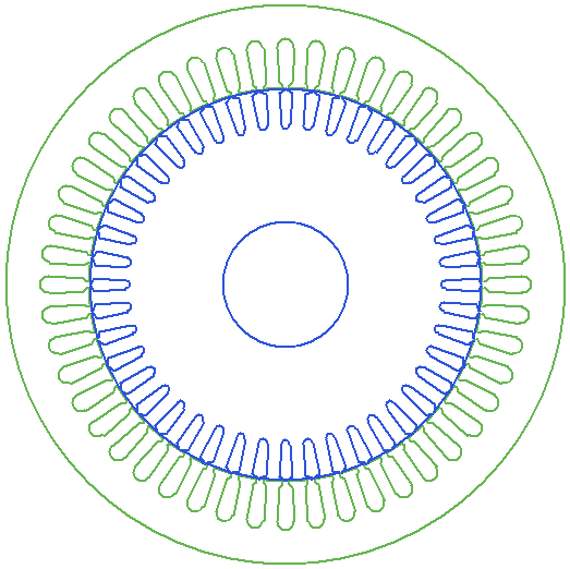
Fig. 6: Design yzd132-8, three phase induction motor, 8 - pole, 48 stator slots, single layer, 44 rotor slots.
STATOR
Apply the settings for the stator. Variables can be used for optimization analysis.
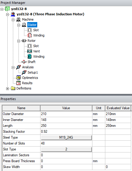
Fig. 7: Define the geometry of the stator and assign stator steel type material.
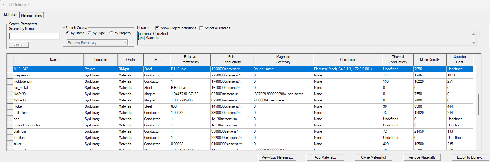
Fig. 8: Select the stator steel type from an industry based material database.
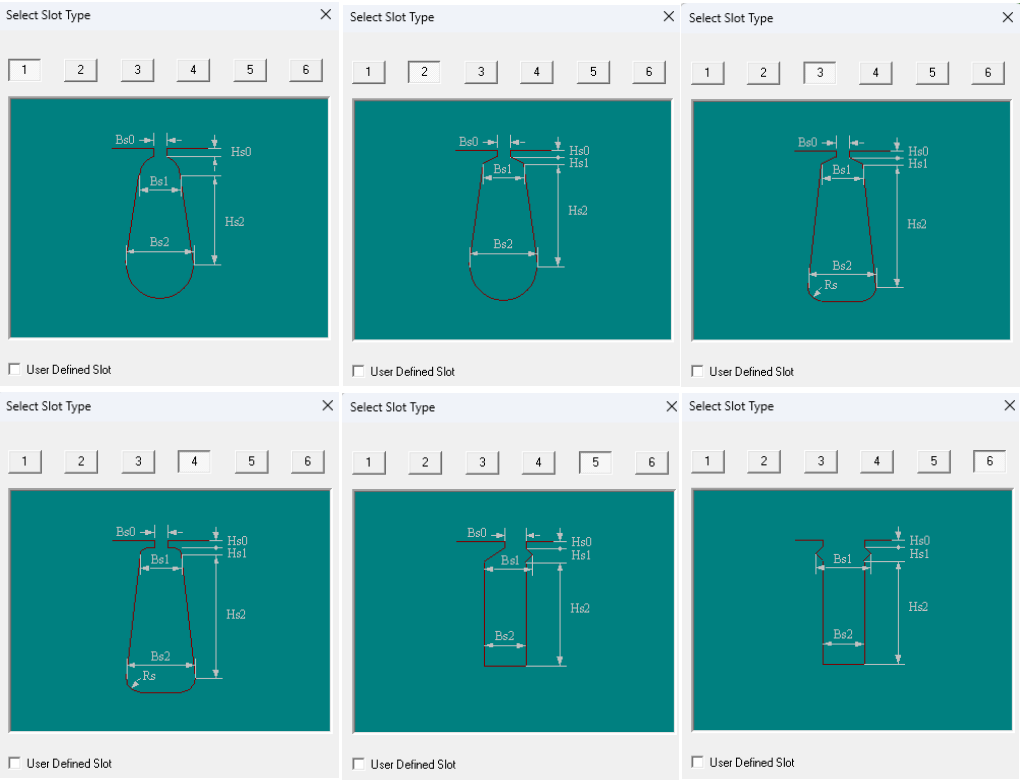
Fig. 9: Select an industry based stator slot type template to design the stator slots.
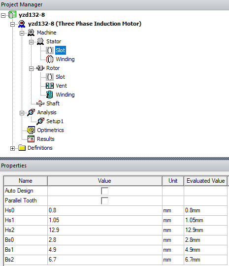
Fig. 10: The stator slot properties available are according to the slot type template selected.
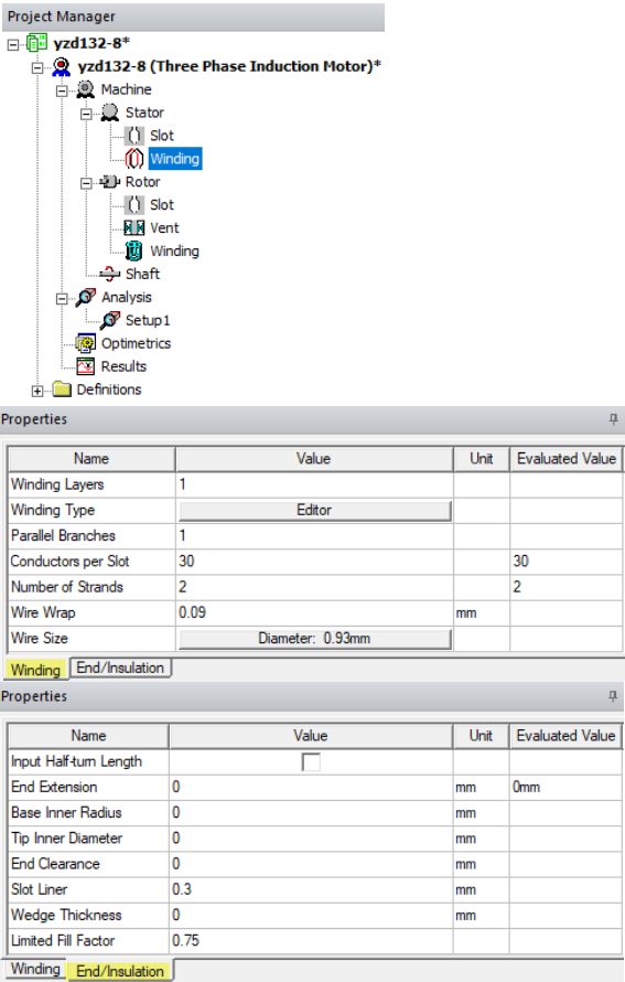
Fig. 11: Design the stator "Winding" and "End/Insulation".
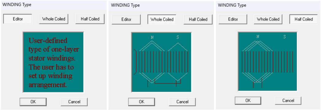
Fig. 12: Choose a "Winding Type" among three options: "Editor" (user defined), "Whole Coiled" or "Half Coiled".
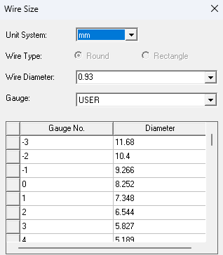
Fig. 13: Choose the "Wire Size" in AWG or apply a user defined gauge.
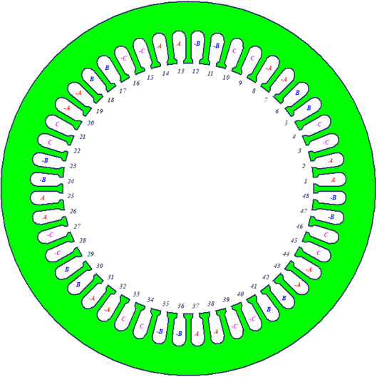
Fig. 14: Slot type #2, single layer, 48 stator slots, 8-pole, 8 - coil groups per phase.
ROTOR
Apply the settings for the rotor. Variables can be used for optimization analysis.
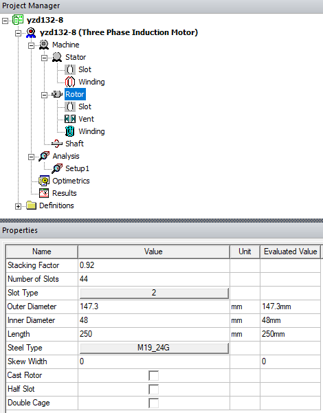
Fig. 15: Define the geometry of the rotor and assign rotor steel type material.
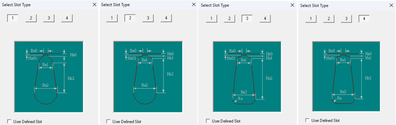
Fig. 16: Select an industry based rotor slot type template to design the rotor slots.
Fig. 17: Select the stator steel type from an industry based material database.
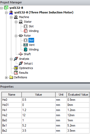
Fig. 18: The rotor slot properties available are according to the slot type template selected.
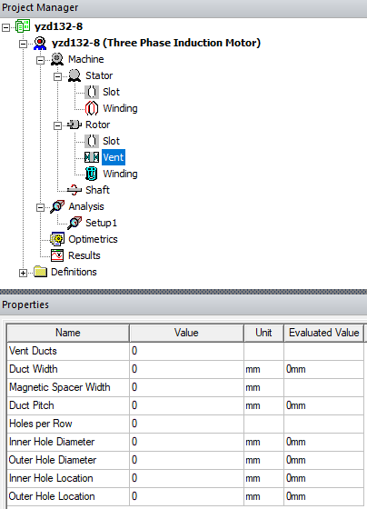
Fig. 19: Design the vent of the rotor.
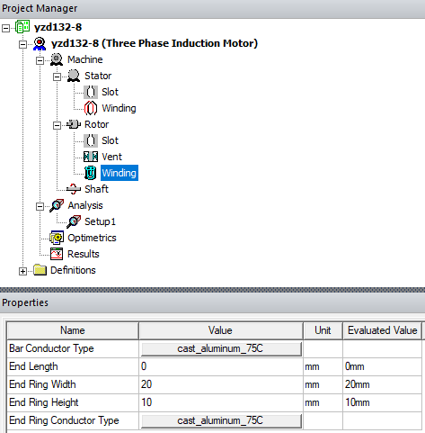
Fig. 20: Design the rotor winding.
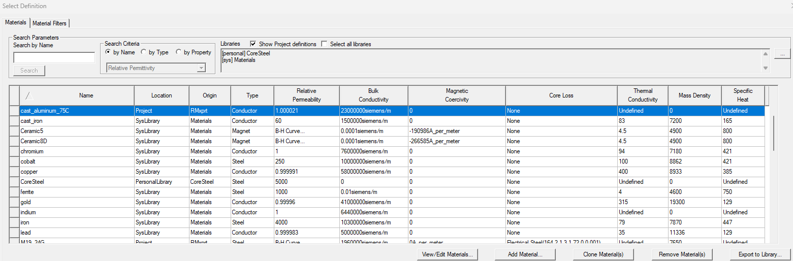
Fig. 21: Select the "Bar Conductor Type" and "End Ring Conductor Type" from an industry based material database.
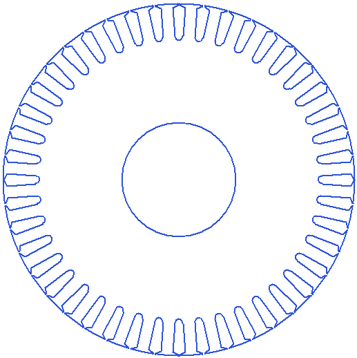
Fig. 22: Rotor: slot type #2, 44 slot, 8 - pole.
SETUP
Select "Setup1" under "Analysis" in the Project Manager as shown below and configure the settings for the analysis. For this motor type there are four "Load Type" options to choose from: Constant Speed, Constant Power, Constant Torque, Linear Torque, and Fan Load. The stator winding can be either Wye or Delta connected.
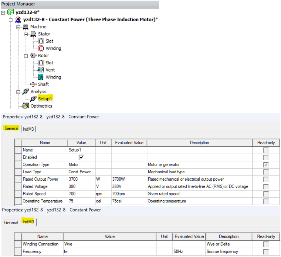 Fig. 23: Choose the load type, apply ratings, select the winding type and set the excitation frequency.
RESULTS
The three phase induction motor model is setup and now we are ready to simulate and analyze results. RMxprt will provide default result parameters and curves, and you are able to use the parameters to derive other parameters and to develop your own curves (plots). With "OptiSLang" under "Optimetrics" you are able to develop efficiency maps but this will not be covered in this blog, but will be covered in a future blog.
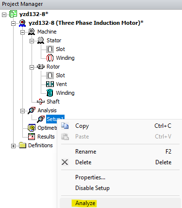
Fig. 24: Right click on "Setup1" and select "Analyze" to run the simulation which completes in seconds.
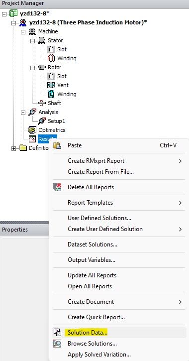
Fig. 25: Right click on "Results" and select "Solution Data" to view "Performance" data, "Design Sheet", and "Curves".
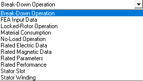
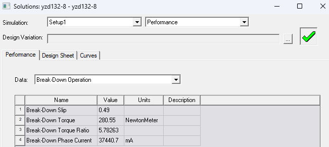
Fig. 26: There are various performance data to choose to view. Here is a view of the "Break-Down Operation" data.
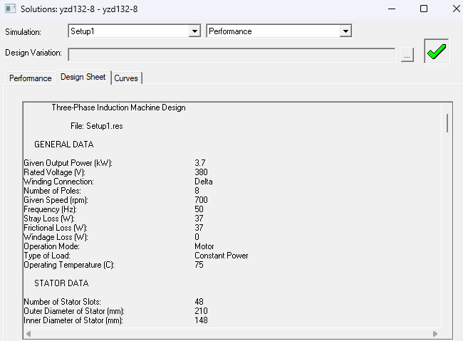
Fig. 27: This is a partial view of the "Design Sheet".
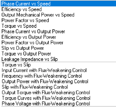
Fig. 28: These are the default performance curves available, and may be derived using results data in expressions.
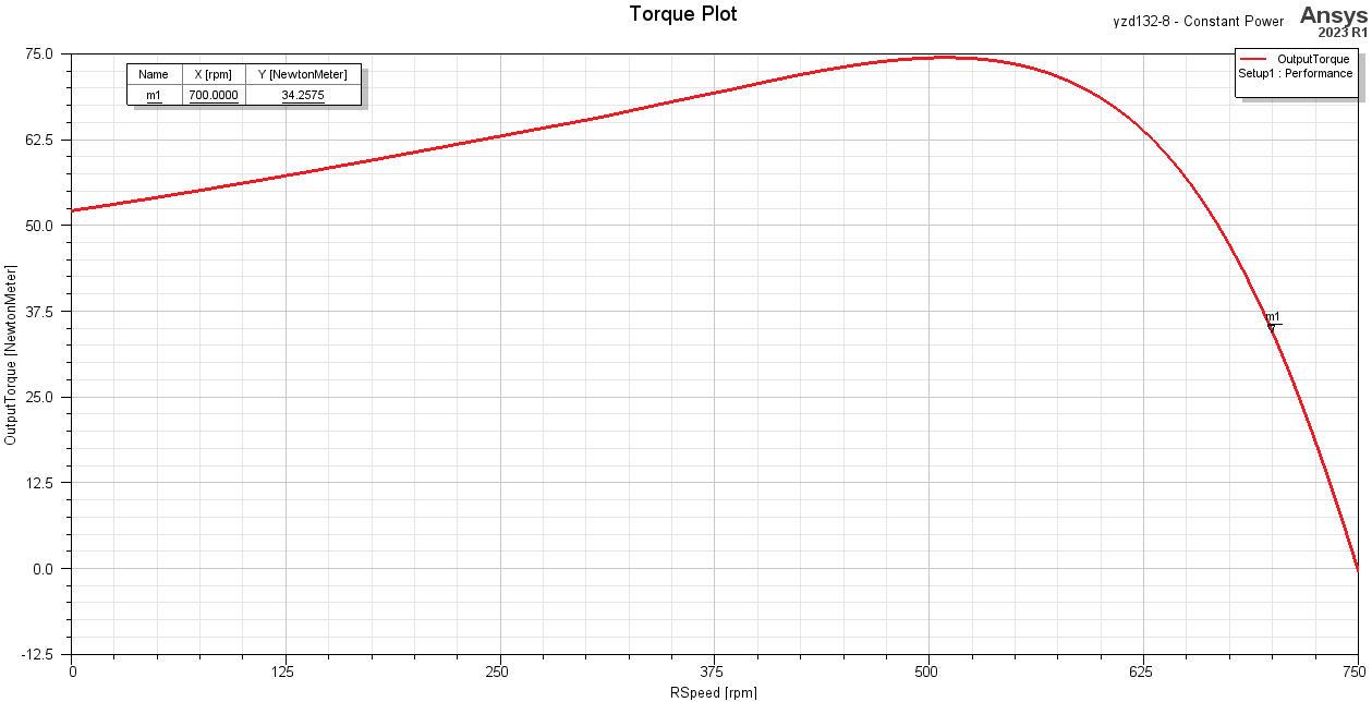
Fig. 29: Output Torque vs Speed curve of the three phase induction motor.
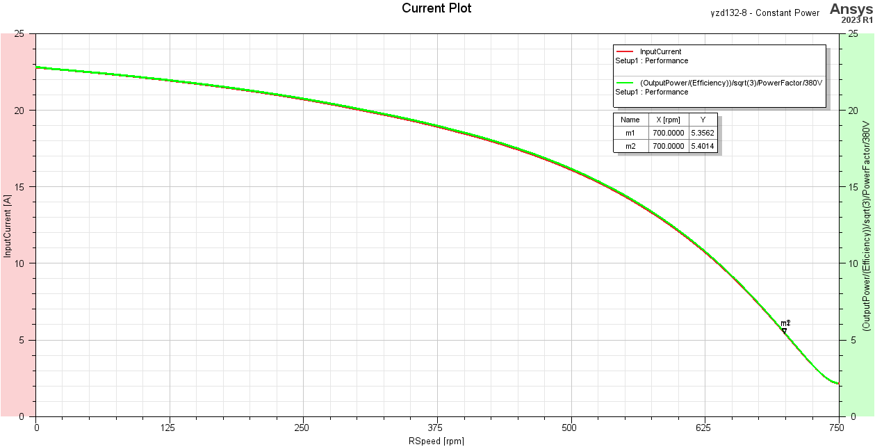
Fig. 30: Default curve of Input Current vs Speed compared to an expression (shown in top right of plot).

Fig. 31: Default Efficiency vs Speed curve compared to an expression (shown in top center of plot).
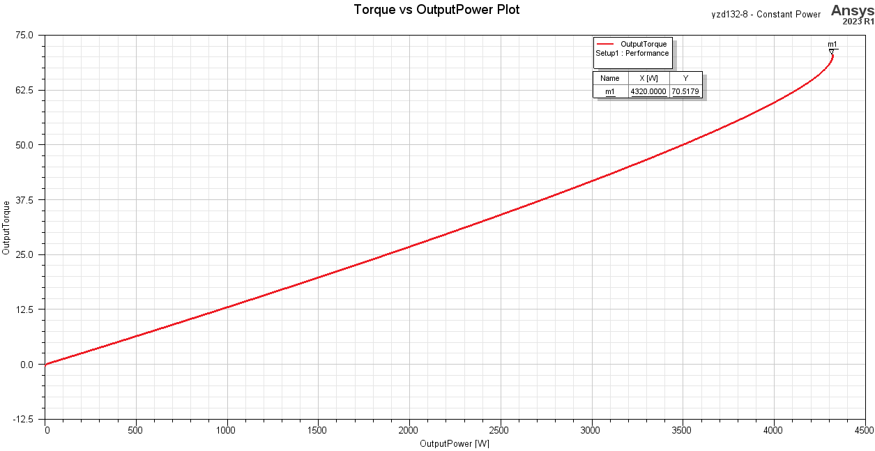
Fig. 32: Output Torque vs Output Power curve derived using default data parameters.
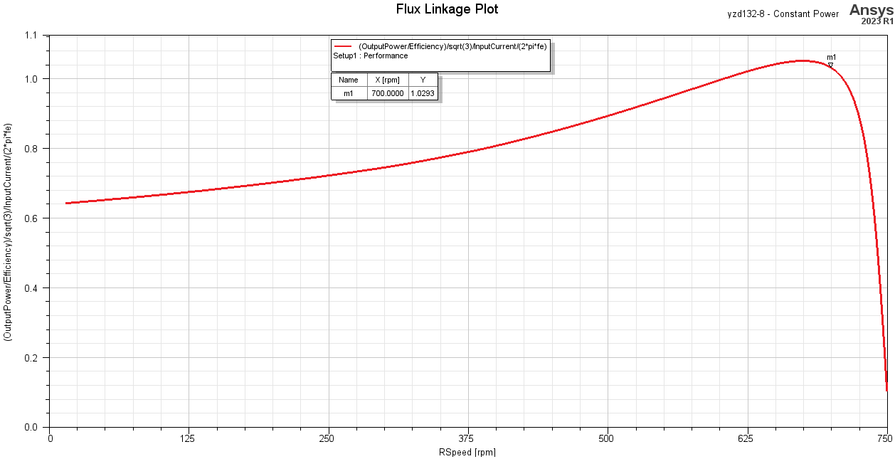
Fig. 33: Flux Linkage vs Speed derived using default data parameters in an expression (shown in top center of plot).
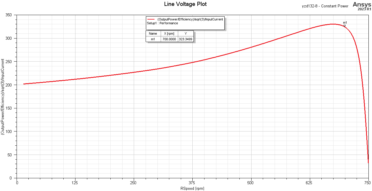
Fig. 34: Induced voltage vs speed plot from default data parameters in an expression (shown in top center of plot).
AUTOMATED MAXWELL FEM MODEL
RMxprt can easily, quickly, and automatically create 2D or 3D FEM models for you with all boundary conditions, excitation settings, and everything else completely setup for you to simulate these models. All you have to do is simulate and analyze the results.
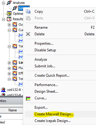
Fig. 35: Right click on "Setup1" under "Analysis" and select "Create Maxwell Design".
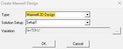
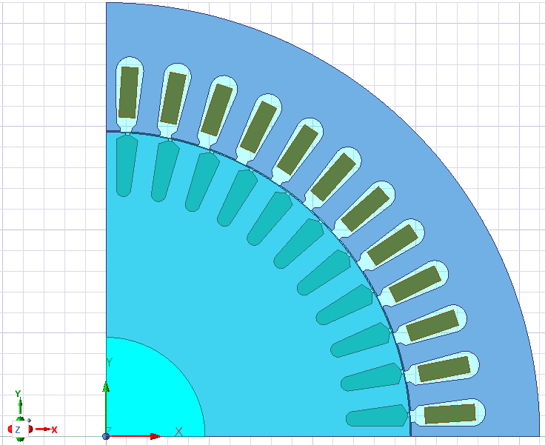
Fig. 36: Choose "Maxwell 2D Design" and in a few seconds RMxprt automatically creates the 2D model shown here. A quarter symmetry model is the default model but this can easily be changed in the properties to be a full model.
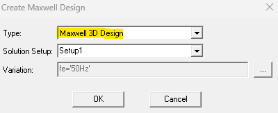
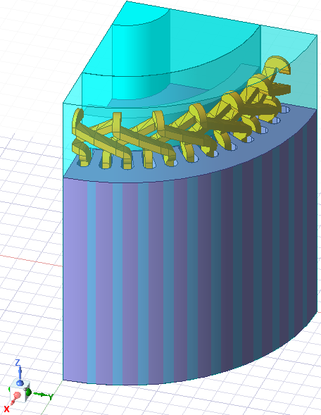
Fig. 37: Choose "Maxwell 3D Design" and in less than 2 min RMxprt automatically creates the 3D model shown here. A quarter symmetry model is the default model but this can easily be changed in the properties to be a full model.
You are invited to visit our YoutTube channel to view the video associated with the blog using the link below:
ABOUT OZEN ENGINEERING INC.
Ozen Engineering is a leading provider of Ansys solutions, catering to a diverse range of industries with a specialization in electronics, semiconductor, biomedical, healthcare, aerospace and automotive applications. Our team delivers personalized solutions to optimize product design and performance by seamlessly integrating Ansys simulation into the product development process. As an elite channel partner of Ansys, we provide best-in-class software tools, consulting, training, mentoring, and technical support.
Contact us to learn about our simulation capability and request a demonstration for us to show you how we can help you with your engineering projects. Ozen Engineering Inc is an Ansys Elite Channel Partner, and we provide training to use Ansys tools, offer consulting services, and sell Ansys software packages.
Visit our website
Give us a call
Send us a message