
Abstract
Obtaining results from simulations can be a tedious task, especially when needing multiple images of different components with different result types. It can be difficult to extract images with consistent view points and angles by hand. We can use the scripting tools provided by ANSYS Mechanical to quickly extract contour images with consistent viewpoints. This blog shows one approach to extracting image results from within ANSYS Mechanical.
Introduction
ANSYS Mechanical’s scripting language uses Python. For the purpose of this post, we only need a basic background in Python to utilize ANSYS Mechanical scripting.
Create Viewpoints
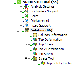
After running your simulation, add your desired results under the solution tree. Name the results in the results tree with distinct key words. These keywords should ideally indicate the angle or characteristic of the view, such as Top, Bottom, Isometric, etc.
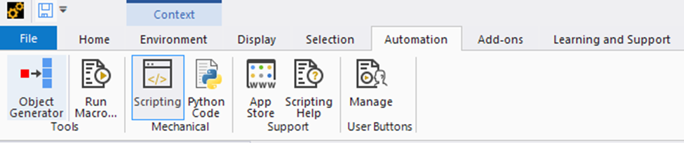
Open up Scripting from the Automation Tab.
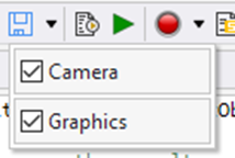
Under the recording drop down menu, enable the camera and graphics options.
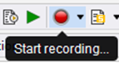
Click start recording, and position the camera to the view point you want.
If you are already in the correct spot, scrolling in and out will generate viewpoints in the script tree.
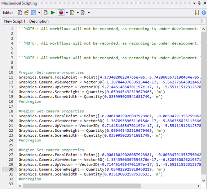
The code to angle the camera to the correct viewpoint will be automatically generated. The viewpoint you want to save for the code will be the final viewpoint generated. In the above image, lines 26 to 32 were the final change to the view I had made, and were what I had saved for future use.
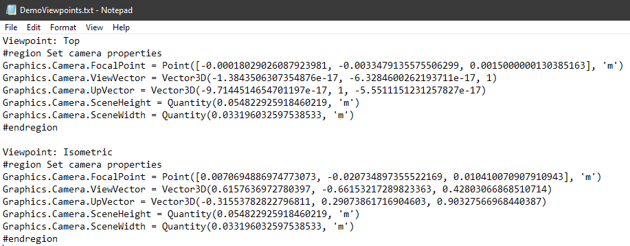
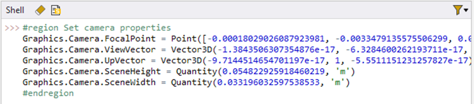
Copy and store the lines of code elsewhere. You can verify that the viewpoint is correct by running it in the shell. Repeat for each desired viewpoint.
Create Script
The following script is how we will extract the image results. You can write and save the script directly within the script window, or write it an external editor and import it later.
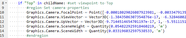
| results = DataModel.GetObjectsByType(DataModelObjectCategory.Result) #loop over the results for result in results: # select and activate the result result.Activate() childName = result.Name if "Top" in childName: #set viewpoint to Top #region Set camera properties Graphics.Camera.FocalPoint = Point([-0.00018029026087923981, -0.0033479135575506299, 0.0015000000130385163], 'm') Graphics.Camera.ViewVector = Vector3D(-1.3843506307354876e-17, -6.3284600262193711e-17, 1) Graphics.Camera.UpVector = Vector3D(-9.7144514654701197e-17, 1, -5.5511151231257827e-17) Graphics.Camera.SceneHeight = Quantity(0.054822925918460219, 'm') Graphics.Camera.SceneWidth = Quantity(0.033196032597538533, 'm') #endregion if "Iso" in childName: #set viewpoint to Iso #region Set camera properties Graphics.Camera.FocalPoint = Point([0.0070694886974773073, -0.020734897355522169, 0.010410070907910943], 'm') Graphics.Camera.ViewVector = Vector3D(0.6157636972780397, -0.66153217289823363, 0.42803066868510714) Graphics.Camera.UpVector = Vector3D(-0.31553782822796811, 0.29073861716904603, 0.90327566968440387) Graphics.Camera.SceneHeight = Quantity(0.054822925918460219, 'm') Graphics.Camera.SceneWidth = Quantity(0.033196032597538533, 'm') #endregion # export the result as a 2D PNG file Graphics.ExportImage("C:\\Desktop\\Images\\" + result.Name + ".png") print "Done with Exporting Results" |
The "for" loop iterates over every result we defined in the solution tree.
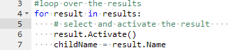
The “if” statements look for a key word in the name of each result in the result tree and executes the command to change the viewpoint for that result. In this example, "Top" and "Iso" were key words that I selected to indicate a top view and an isometric view. You can modify the keywords and the viewpoints to fit your needs. You can also add more "if" statements to add additional viewpoints.
After the viewpoint is set, the program saves the image of the result to the designated folder.
![]()
The line with "Graphics.ExportImage" will export the image to the folder location you have designated, and name the image accordingly. It is important to have unique names for every result in the solution tree, since it will overwrite existing images.
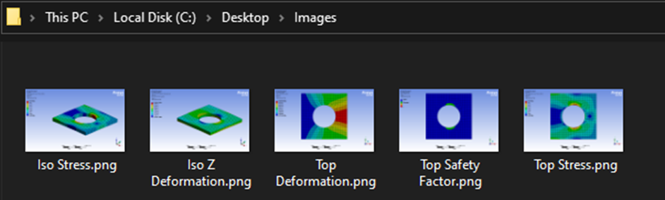
The below image shows how you can expect the images to appear in your designated folder.
Conclusion
Scripting in ANSYS Mechanical is a powerful tool that can save time and increase the quality of your simulation reports. This blog provides an approach to automating the process of extracting image results from ANSYS Mechanical.
Here are some additional blogs that cover related scripting topics:
