In this Blog I will show two examples of how to simulate a Wireless Power Charger using Ansys Maxwell. The Maxwell FEM model is excited with an external Maxwell circuit, and in the second example I will show how to use a Simplorer model to couple with the Maxwell model using a Reduced Order Modelling (ROM) circuit block, which dynamically links the two models. Capacitor circuit elements are computed and added to the windings to achieve the resonance required for maximum wireless power charging.
In these examples the selected excitation frequency is f = 150 kHz, and the Eddy Current solver (Frequency Domain, Sinusoidal, Steady State) is used.
MAXWELL FEM MODEL
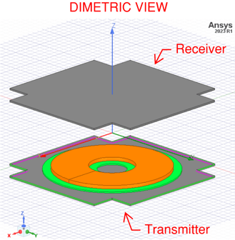
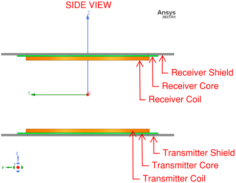
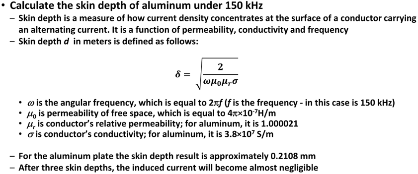
SKIN DEPTH OF SHIELDS AND MESH ELEMENT SIZE
In this model the thickness of the shield (aluminum) is 5 mm, and the skin depth is 0.2108 mm. The skin depth is much smaller than the dimensions of the shield, therefore, the losses due to induced Eddy Currents in the shield are small.
INDUCTANCE
To compute (or extract) inductances of the windings under linear operation, we can apply a small amount of current excitation, 1A amplitude, for example. Inductance depends on the geometry of the winding and core, and on the core's permeability, and not on excitation phase or magnitude, in linear system or operating region. The inductances L(winding1, winding1) and L(winding2, winding2), shown below, are the self inductances of Winding-1 and winding-2, respectively. Also, the inductances L(winding1, winding2) and L(winding2, winding1), shown below, are the mutual inductances between Winding-1 and winding-2, respectively.

DETERMING CAPACITANCE AND DC WINDING RESISTANCE
The dc resistance of the windings are computed manually, to consider each winding strand, using the familiar resistance equation for a conductor of circular cross-section, shown as Rdc below. The capacitance to connect to each winding is computed by using the computed inductance and the selected excitation frequency f in the equation shown as Rc underneath.
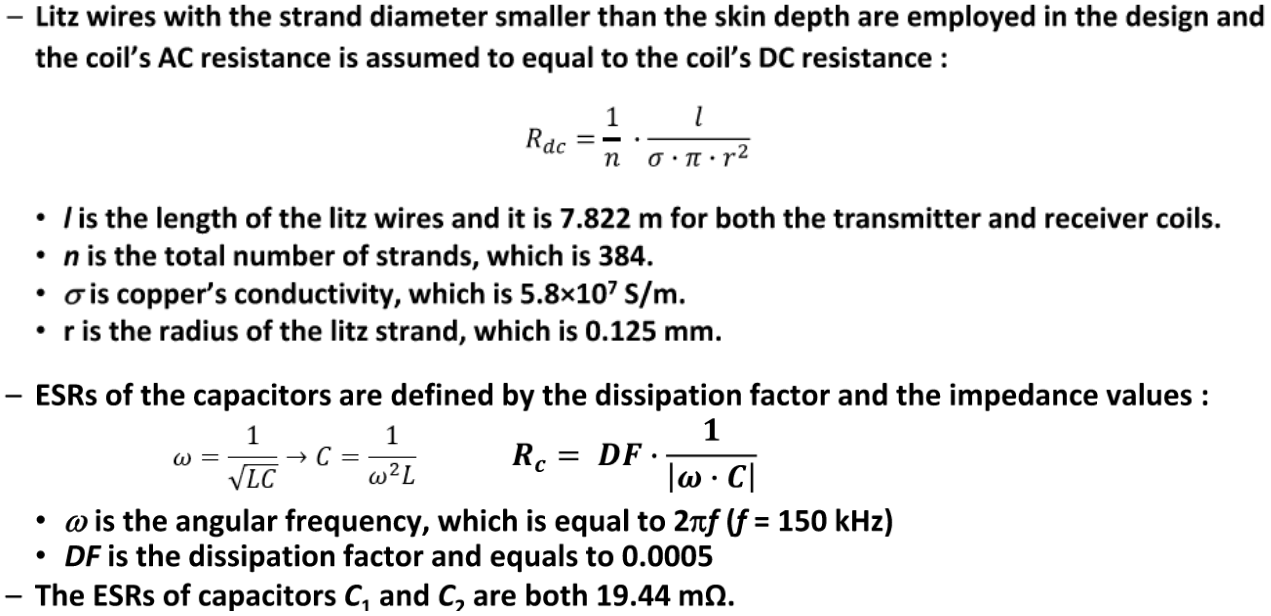
where L(winding1, winding1) replaces L for winding-1 and L(winding2, winding2) replaces L for winding-2.
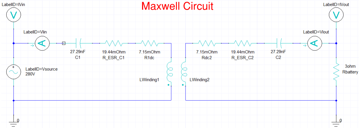
MAXWELL CIRCUIT EXCITATION EXAMPLE- FREQUENCY RESPONSE
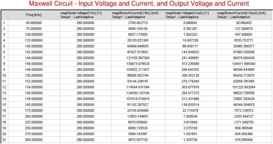
A Maxwell Circuit is created below with the computed capacitances, including Equivalent Series Resistanc (ESR), connected in series with the windings, to establish resonance. The winding matrix results contain the impedance of the core and shield, and the resistance of the windings are computed manually, to consider each winding strand.
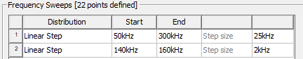
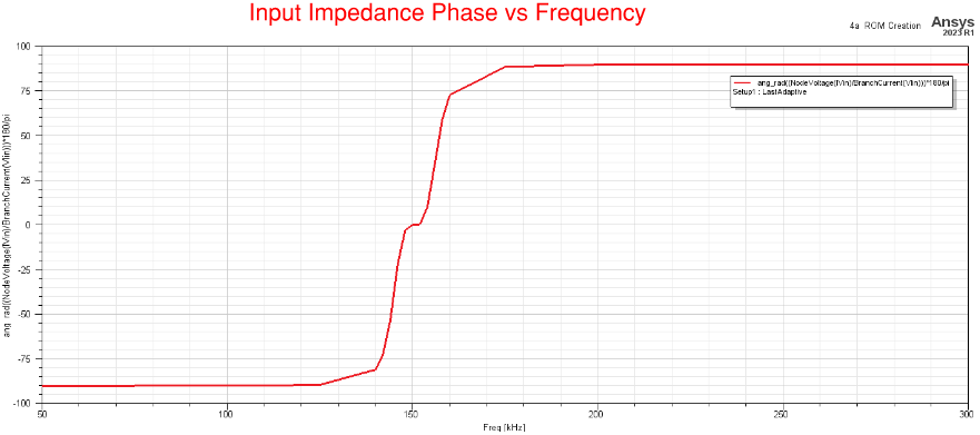
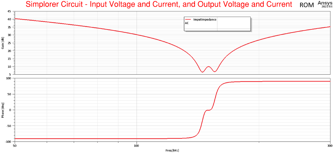
The following two frequency sweeps are used. A second frequency sweep with finer resolution is necessary to capture the "Bifurcation Phenomena" near the resonant frequency (150 kHz).
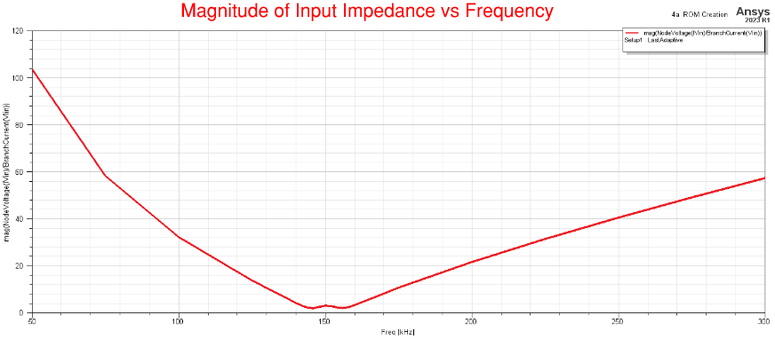
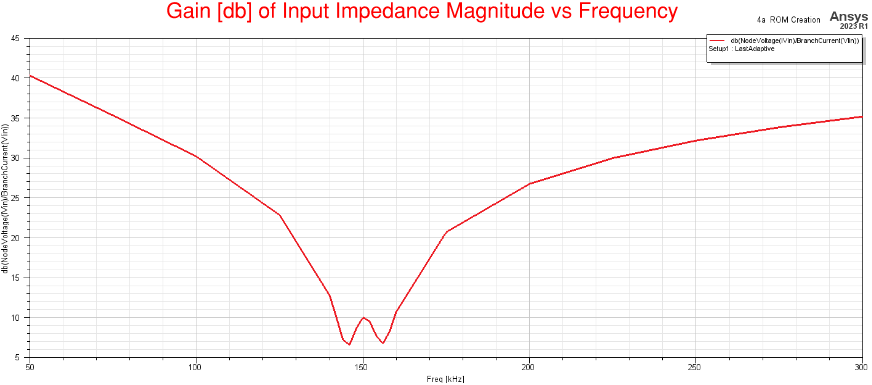
Notice how the magnitude (or Gain) of the Input Impedance is low near the resonant frequency, and also at this frequency the phase is zero, and at this resonant frequency maximum power charging occurs wirelessly.
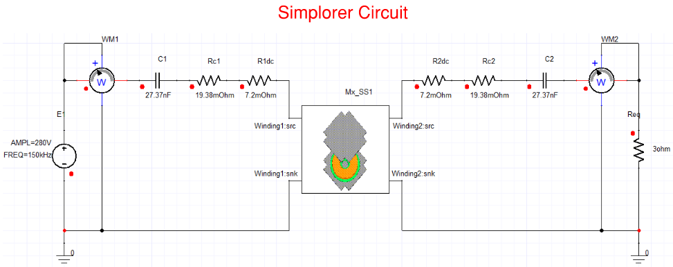
SIMPLORER CIRCUIT EXCITATION EXAMPLE - REDUCED ORDER MODEL (ROM) - FREQUENCY RESPONSE AND TRANSIENT ANALYSIS
Simplorer can be coupled with Maxwell to obtain Transient Analysis results, in addition to Frequency Response results. A Reduced Order Model (ROM) circuit block, dynamic link component, can be used in Simplorer to represent the resistances of the windings, core and shields. However, we can set the conductivity of the windings in Maxwell, lumped winding objects, to be much higher (x1000) than what the actual value is, as in this example, so that Maxwell would ignore the winding resistances in the model. Then the winding resistances can be computed manually, taking into account each winding strand, and put these resistances in series with with the ROM circuit block which would now only represent the resistances of the core and shields.
The ROM is created by following the steps highlighted underneath.
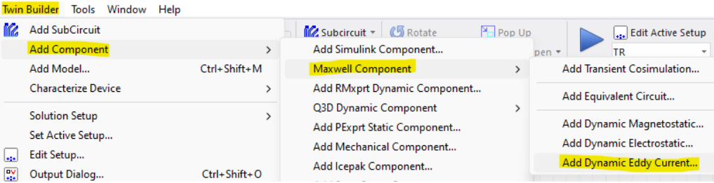
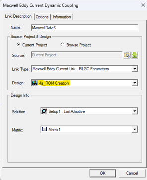
The Maxwell model still needs to be excited externally using the Maxwell circuit in the previous example. After creating the Simplorer circuit model with the ROM circuit block as shown below, run the simulation and Simplorer will initiate to solve the Maxwell model. Once, the Maxwell model is solved, Simplorer will receive the impedance values for the core and shield. Then when the simulation is completed you would be able to plot Frequency Response and Transient Analysis results. You can verify that the Frequency Response results from Maxwell match with the results from Simplorer.
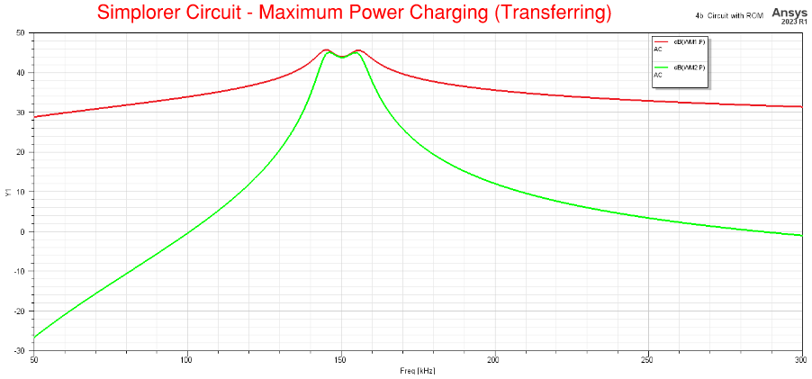
Notice in the plots below how the Gain of the Input Impedance is low near the resonant frequency, and also at this frequency the phase is zero, and at this resonant frequency maximum power charging (transfer) occurs wirelessly. These results are equivalent to the results from the previous example.
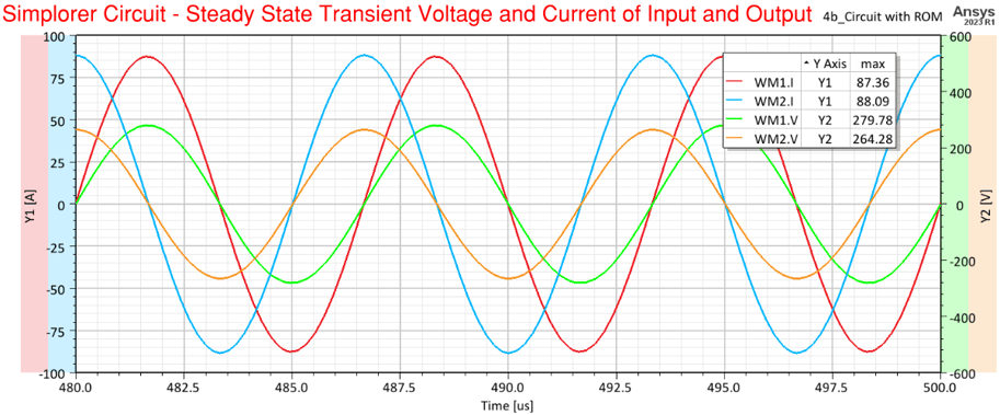
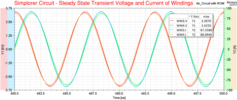
Transient Response plots of the model coupled with Maxwell are easily obtained using Simplorer. The plots below show the voltages and currents of the input, output, and of the windings. Notice how the current in winding-2 leads by 90 deg the current in winding-1. Power is transferred from the source through winding-1 and wirelessly (even without a core in between) to winding-2.
That is all for this blog.
Here is the link to the video associated to blog:
ABOUT OZEN ENGINEERING INC.
Ozen Engineering is a leading provider of Ansys solutions, catering to a diverse range of industries with a specialization in electronics, semiconductor, biomedical, healthcare, aerospace and automotive applications. Our team delivers personalized solutions to optimize product design and performance by seamlessly integrating Ansys simulation into the product development process. As an elite channel partner of Ansys, we provide best-in-class software tools, consulting, training, mentoring, and technical support.
Contact us to learn about our simulation capability and request a demonstration for us to show you how we can help you with your engineering projects. Ozen Engineering Inc is an Ansys Elite Channel Partner, and we provide training to use Ansys tools, offer consulting services, and sell Ansys software packages.
Visit our website
Give us a call
Send us a message